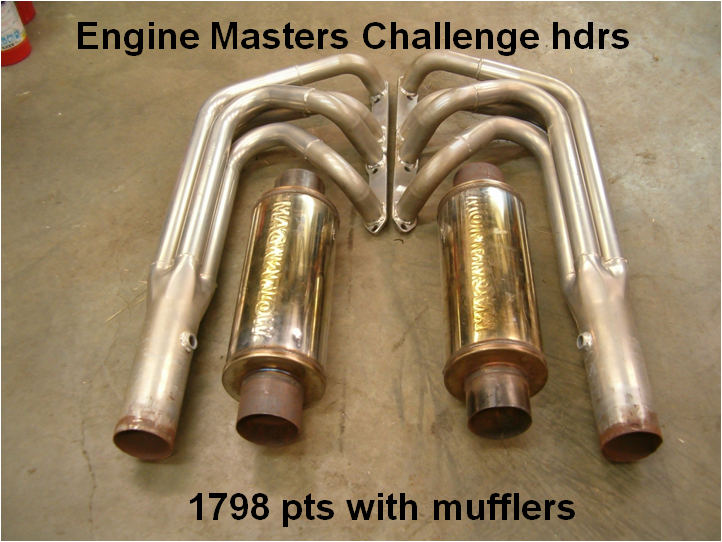
When the question came up as to how well some of the various exhaust and header designs perform on the Ford Y-Block family of engines, the 312 dyno mule was again put to work in doing an extensive exhaust system test. Twenty-four different exhaust systems ranging from single exhaust to stepped headers were tested with each system being tried in a variety of configurations. Where possible, the different exhaust systems were also tested with and without mufflers and a variety of head-pipe lengths. When mufflers were used, they were sized according to the pipe size going into them which required having a variety of chambered mufflers on hand for this test. Except in the case of where the headers used for the 2010 EMC competition were used, mufflers were a deterrent for making additional power. While there are mufflers out there that are not a detriment for power production, those simply were not on hand for this test.
The engine used for the testing presented here is a +060 over 312, cast pistons 0.025” in the hole, the rotating assembly balanced, a Crower Monarch cam with 238° @ 0.050”, ground on 110° lobe centers, and 0.461” lift at the valve after valve lash while using Harland Sharp 1.6:1 roller rockers. A stock Mummert aluminum 4V intake manifold topped with a 2” dual oval carb spacer and 750 cfm Holley carb feeds air and fuel to the engine. A MSD distributor and wires along with Autolite #45 spark plugs gapped at 0.035” keeps the cylinders firing. An Innovators West harmonic damper is being used on this engine after finally abusing the original damper to the point that the rubber started coming apart. The damper was changed out long prior to doing the exhaust tests. The static compression ratio is 9.6:1 using a pair of heavily milled but mildly ported ‘posted’ ‘G’ heads. The porting and milling were worth an additional 18 HP over a stock set. The key here was to eliminate the cylinder heads as the bottle neck for power production so that any differences in exhaust systems could be more accurately evaluated. A considerable amount of thought went into how to present this data. While graphs give a good visual, they can get very busy quickly if trying to show several tests on a single graph. A chart format is ultimately decided upon as it gives a quick overview of all the different exhaust systems at a glance. To get a better feel for the overall performance of a given exhaust system, a scoring format is used as it rates the test over a rpm range rather than looking at individual peak hp or torque values. For this, the rpm band for the tests was maintained at 2500-5500 rpm. While the tests could have started at 2000 rpm, this is hard on the engine and especially the main bearings so 2500 rpm was the starting point. The scores are calculated by adding the average of the torque and hp values together, multiplying by 1000 and dividing by the cubic inch (322). In the case of a tie, the peak hp value is then used as the tie breaker. In the following chart, the exhaust systems are listed in the order they scored from lowest to highest. Where exhaust systems were tested with several configurations, the highest score from those tests is the one listed.
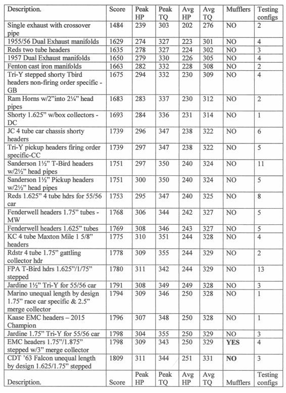
As can be observed, it’s not necessarily about the peak numbers. In some instances, the scores on some of the exhaust tests are found to be higher but with lower peak numbers than another set of exhaust tests with higher peak numbers. For drivability purposes, the scoring format gives a better indicator of overall performance rather than using a peak number.
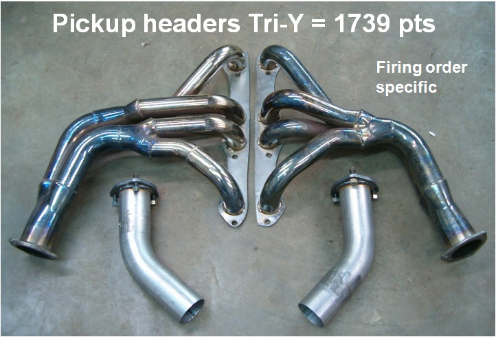
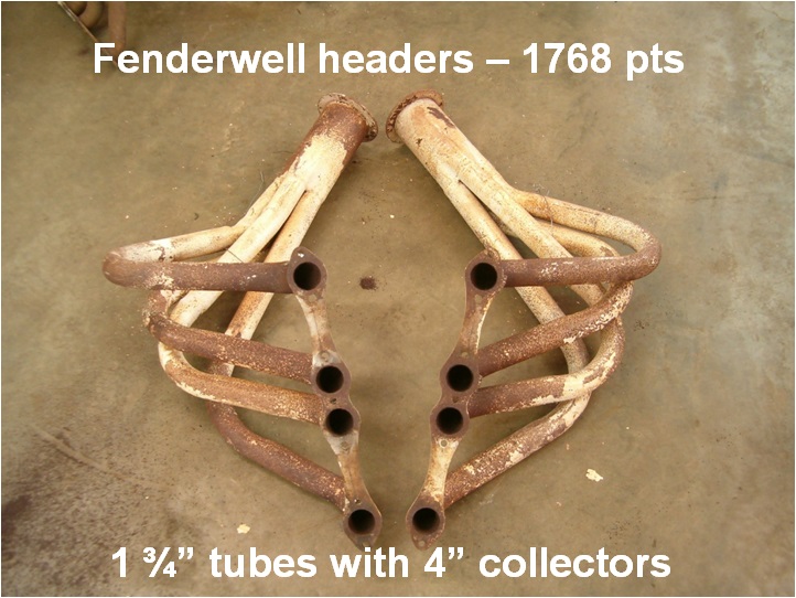
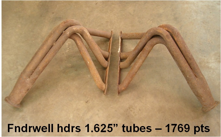
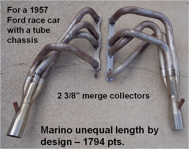
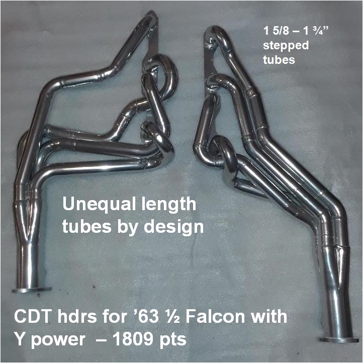
The two sets of headers that were built with ‘unequal length tubes by design’ do show some promise as both sets are in the high range of values of all the exhaust systems tested. The idea behind those unequal length tubes is to more evenly distribute the pressure buildup at the collector that occurs when the two cylinders on each bank fire in a back to back fashion. On the Ford Y, it is cylinders 8 & 6 on the left bank and cylinders 2 & 1 on the right bank where those pressure build ups originate. To help equalize those pressure build ups that occur at the collector as a result of the Y firing order being what it is, the tubes for cylinders 2 & 8 are made intentionally shorter while the tubes for cylinders 1 & 6 are made longer by design. The remaining cylinders all remain at a standard and equal length. By doing the tube lengths in this fashion, the exhaust pulses of cylinders 2 & 8 are permitted more time to evacuate from the collectors before the pressure pulses from cylinders 1 & 6 come in behind them. The firing order nuance where there are two cylinders firing one after the other on each bank occurs on all V8 engine designs. This is sometimes compensated for by designing a 180° header where a pair of tubes cross over (or under) the engine so that each collector is truly alternating from side to side in conjunction with the exhaust pulses that enter them. Very few vehicles can benefit from a true 180° header design simply due to chassis limitations. For the Ford Y, the firing order is such that the cylinders requiring shorter tubes are already closer to rear of the engine and subsequently the collector thus making the headers somewhat easier to fabricate when going for this particular design.
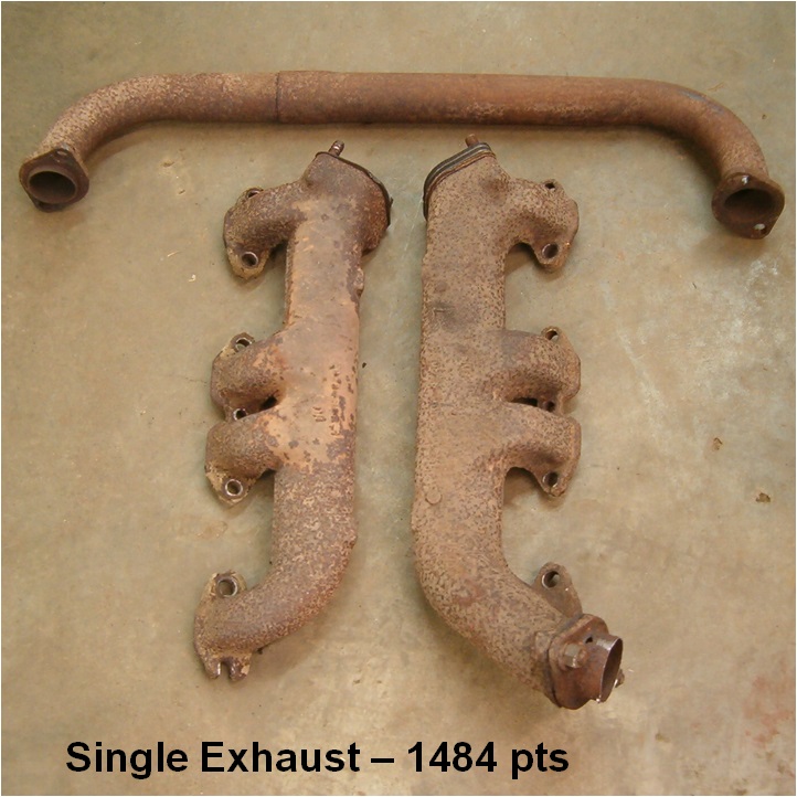
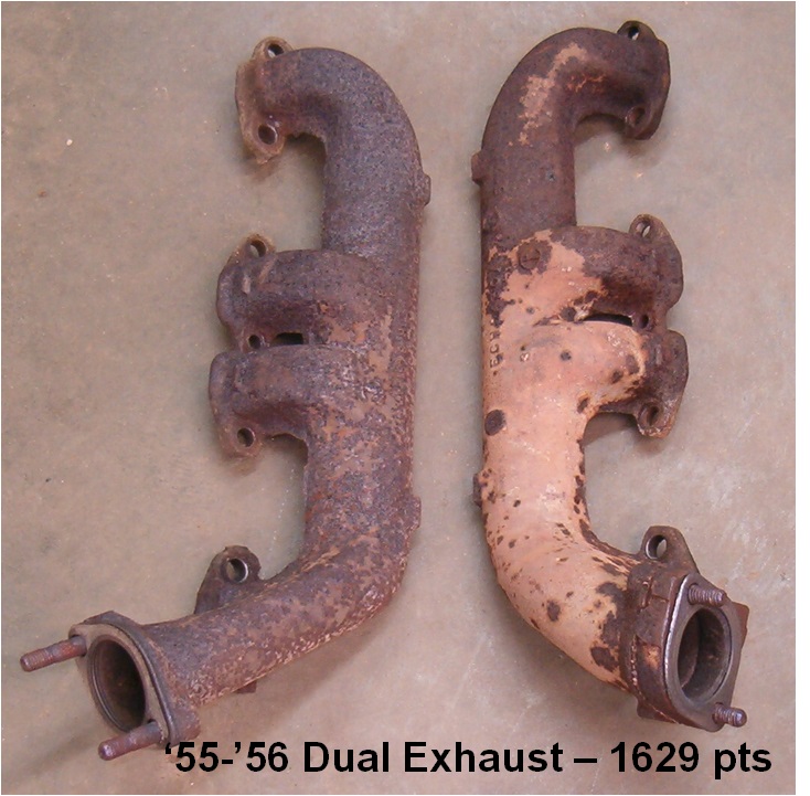
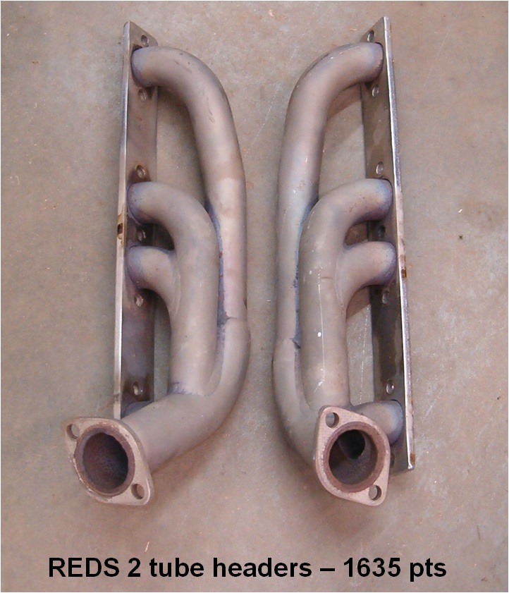
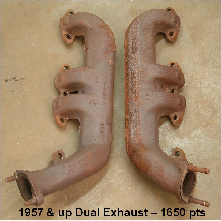
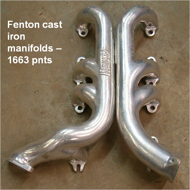
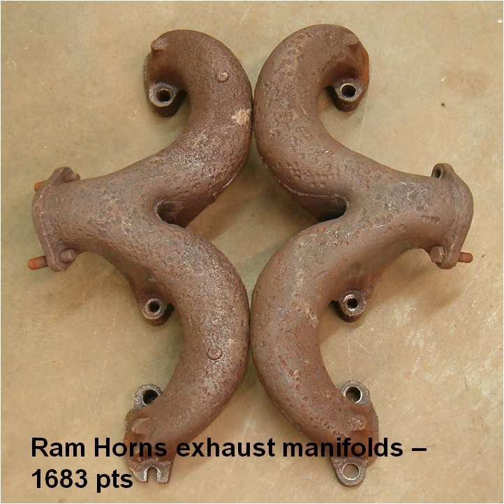
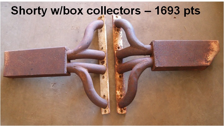
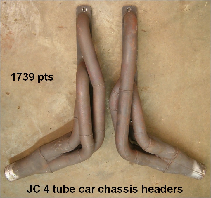
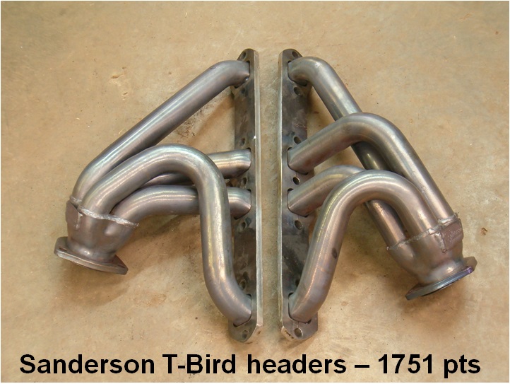
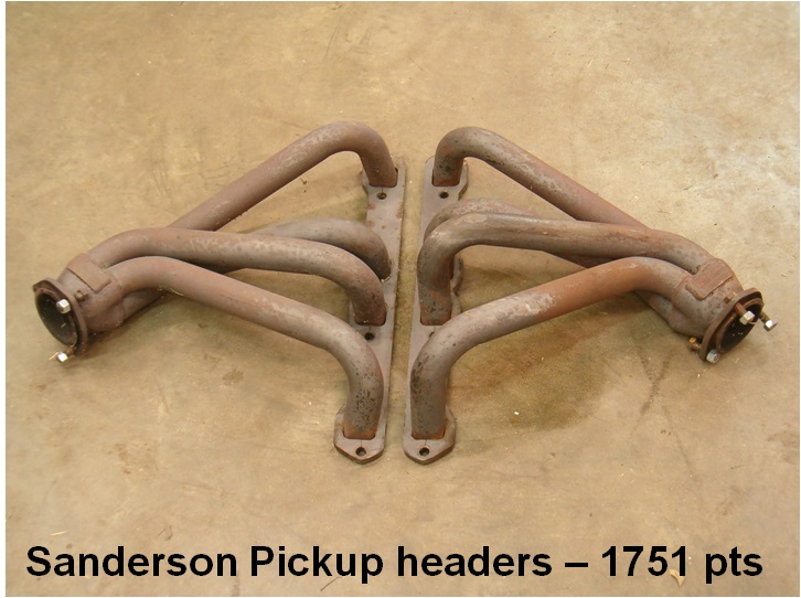
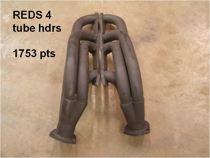
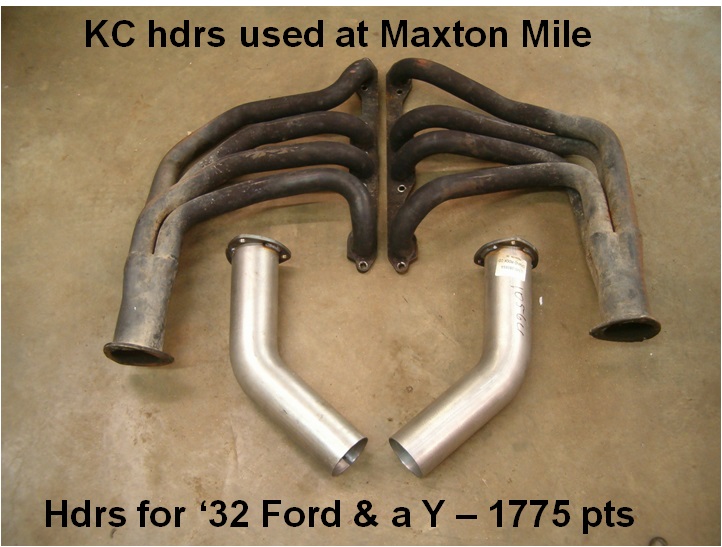
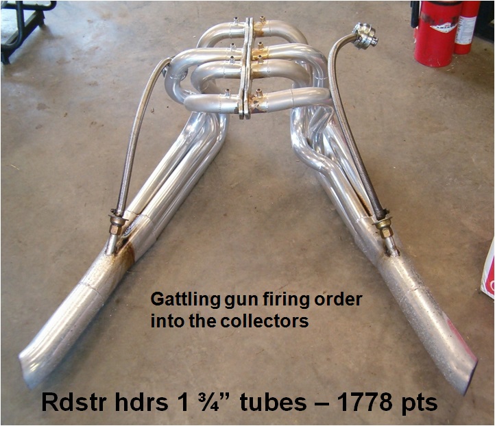
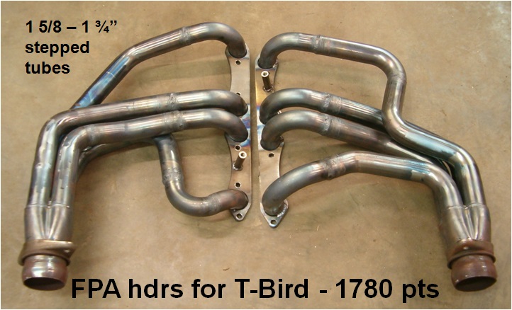
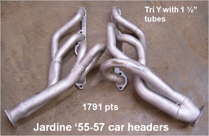
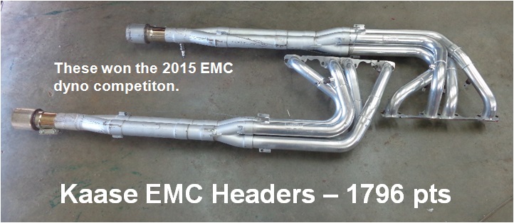
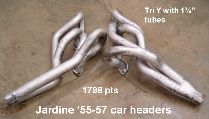
Always keep in mind that this header test was performed on the same engine with no modifications being made to the engine itself to complement a particular header design. That’s all fine and good for this particular test but these same headers tested on engines modified differently will have different results. Cubic inches and the various modifications performed to a particular engine will dictate special header construction parameters for an engine. For a street engine running through a full exhaust system, then many of the headers will be close in performance to each other although there may be obvious differences in tube diameters, lengths, and collectors. For engines using full exhaust systems including mufflers, then the whole system must be taken into consideration. What follows are pictures of the various exhaust manifolds and headers tested. They are pictured in the order in which they scored from lowest to highest.
As Frank Rice so eloquently mentioned about this series of testing, it was indeed exhausting. All for now and happy Y motoring. Ted Eaton.
This article was previously published in The Y-Block Magazine, issue #161, Nov-Dec 2020.