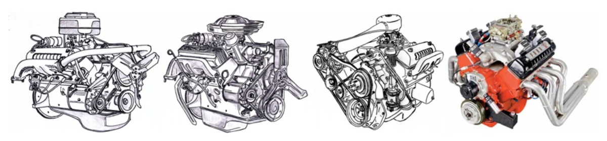
Part of the blueprinting process during any engine buildup will include degreeing in the camshaft. This operation is performed to insure the camshaft is phased or installed at the desired position in relation to the piston sitting at TDC. While degreeing in the camshaft during its installation may seem to be an activity reserved just for the race engines, the fact remains that it’s just as important on the daily driver applications as it is for high performance engines.
A camshaft being off just a few degrees can lead to tuning and performance issues as well as poor fuel economy. The more serious cam phasing problems can include a lack of compression or the complete opposite where detonation issues come to the forefront and must be dealt with. If problems with engine performance are present once the engine is up and running and the camshaft has not been degreed in, then this is an area that becomes a question mark and may have to be revisited. Degreeing in the camshaft during the initial engine build process is much easier on the engine stand than having to perform the operation after the engine has been installed in the vehicle.
Manufacturing variances are why the camshaft must be degreed in. The crankshaft key slot, the camshaft snout key or dowel pin, the crank gear keyway, and the camshaft gear keyway or dowel hole all have a given amount of variability during their manufacture. Added to this are the variances in lobe grinding on the camshaft itself that can also occur. While some of the manufacturing variances will have both positives and negatives involved thus cancelling out some of those variances, stack-ups are where the real problems begin. Stack-ups are when those variances are all positive or negative in nature. These simply add together creating a significant number of degrees in which the camshaft phasing can be ‘off’. While it’s unusual to see engines with as much as eighteen degrees of camshaft error with the gear timing marks giving every indication that all is ‘good’, it does happen. And this is assuming that the camshaft lobes themselves are all ground consistently and as stated on the camshaft specification sheet. That’s another subject that will be touched upon much later.
Before getting into the mechanics of what is actually involved in the cam degreeing process, the terminology must be clarified. Here are some of the common terms.
 Click on picture for larger image.
Lobe centerline angle – This is the total number of degrees between intake and exhaust lobe centers divided by two. This value is controlled by the cam grinder and may also be referred to as the ‘as ground lobe centerline angle’.
Intake lobe centerline angle – This is the number of degrees from the center of the intake lobe to piston TDC. This value is dictated by the variables that occur during the installation process. It is the deviation of this number from the as ground lobe centerline angle number that is most often used to describe the amount of advance or retard in which a camshaft is installed.
Exhaust lobe centerline angle – This is the number of degrees from the center of the exhaust lobe to TDC. This value changes inversely to the intake lobe centerline angle as the camshaft is being installed. The exhaust lobe centerline and intake lobe centerline numbers added together and divided by two will always equal the ‘as ground lobe centerline angle’.
Straight up – This refers to installing the camshaft on the ‘as ground’ lobe centerline angle. The number of measured degrees between the center of the exhaust and intake lobes will be equal. Simply aligning the reference marks on the timing set does not dictate that the camshaft is installed straight up nor does it indicate exactly the number of degrees that the camshaft is installed either advanced or retarded in relation to TDC. The gear timing marks being aligned simply indicates aligned timing marks and does not give any information regarding where the camshaft is actually installed.
Advanced – This is where the camshaft is installed so the timing events occur earlier than if the camshaft is installed straight up. If a camshaft is advanced, the number of degrees between TDC and the intake lobe centerline will be less than the number of degrees between TDC and the exhaust lobe centerline. These two values added together and divided by two will still add up to the advertised lobe centerline angle though.
Retarded – This is the opposite of the advanced scenario and is where the camshaft is installed so the timing events occur later rather than earlier.
TDC – Top Dead Center – This is where the piston is at the top of the bore. This doesn’t have to necessarily be the #1 piston but that is the piston that’s normally referenced during the camshaft degreeing in process. Keep in mind that a piston will sit at TDC for several degrees due to the rock in the connecting rod when it’s at full arm extension. More on how to find ‘exact TDC’ will be covered later.
TOOLS REQUIRED.
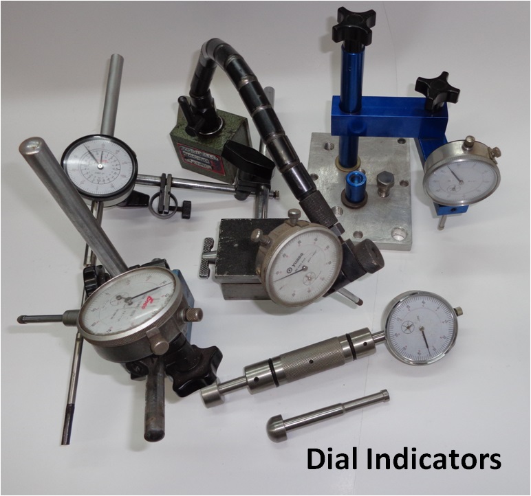
The bare minimum of tools necessary to degree in a camshaft will include a degree wheel and a dial indicator capable of measuring up to 1.000”. The dial indicator ideally needs an extension on it that’s long enough to reach the lifters. A fixture or strap of steel for use as a piston stop can also be beneficial depending upon the methodology being used for determining exact TDC. For the dial indicator, some form of magnetic stand or fixture will be necessary to hold the dial indicator perpendicular to the valve lifter and/or piston.

Click on pictures for larger image.
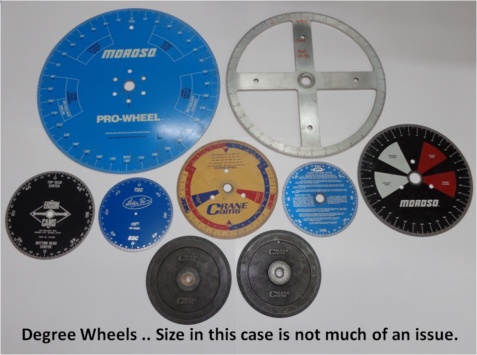
Degree wheels are available in a multitude of diameters and degree readings. They all share a TDC and BDC but how they are numbered in between those two locations may differ. Using larger diameter degree wheels does allow for a greater degree of accuracy but wheels as small as nine inches in diameter can be used with a high level of confidence. It’s important that the locating hole in the center of the wheel be appropriately sized for the bolt that’s being used to attach it to the crankshaft snout. Having a hole that’s too large for the bolt can allow for some sloppiness and inaccuracy in the readings. Many degree wheels if purchased new will include bushings so that varying sizes of bolts can be used. In lieu of using bushings, the underside of a bolt head can be machined with a register so that the degree wheel hole matches the machined bolt head underside.
Click on pictures for larger image.
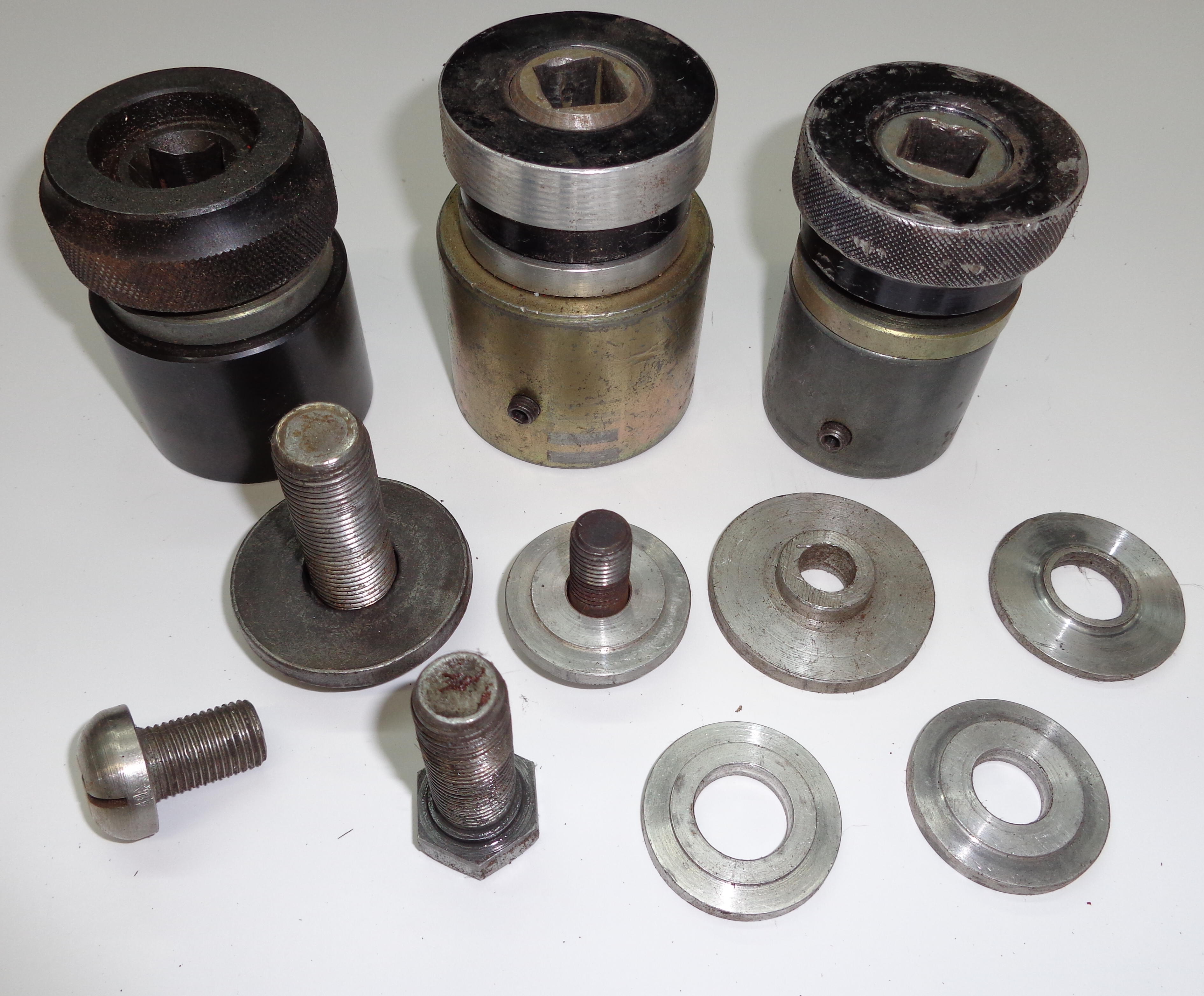
Also required will be a sleeve, nut, or other apparatus for the crankshaft snout so that the crankshaft can be turned without disturbing the degree wheel which is fastened to the front of the crankshaft. Use of a pipe wrench to turn the crankshaft at the unprotected snout is highly frowned upon. While slightly cumbersome, extended bolts in the flywheel flange of the crankshaft in conjunction with a long bar can be used to turn the crankshaft. It’s important that the engine be able to be turned over without disturbing the degree wheel. Using the bolt that fastens the degree wheel to the engine cannot be used to turn the engine over as that can unintentionally move the degree wheel once it has been set.

Click on picture for larger image.
INITIAL PREPARATION.
For the Ford Y-Block family of engines, the lifters, camshaft, and timing set needs to be already installed prior to attaching the degree wheel to the crankshaft. For other engines where the lifters can be top loaded, only the camshaft and timing set needs to be initially installed. This is so that the degree wheel is not disturbed by installing the camshaft and/or the timing set after the fact. For the Ford 292/312 family of engines, the chain is installed on the gears so that there are twelve pins between the gear dots and those pins will be on the oil filter side of the engine. For other engines, the dots on the gears are centered and aligned with each other through the centerline of the cam and crankshaft journals. If in doubt on how the timing gears are initially aligned, simply consult an engine manual for the particular engine being worked on.
It’s assumed at this point that the crankshaft and at least one piston assembly is installed within the block. That piston does not necessarily need the rings on it but the rings being already installed will help to keep the engine from turning over too easily. Most camshaft degreeing takes place with the engine short block already assembled. Ideally, once the camshaft with its corresponding timing set has been degreed in, then it should not be removed to eliminate the risk that the camshaft is reinstalled differently if not re-performing the cam degree in process again.
FINDING ‘Exact’ TDC.
Much emphasis is placed on getting the TDC on the degree wheel properly located. This is simply due to all other measurements being based off of this. Any error in locating exact TDC will be transferred as error in the camshaft degreeing in process.
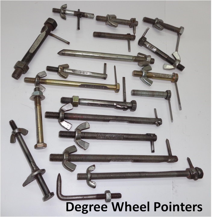
There are several different methods in which to determine the exact TDC. I’ll be concentrating on those methods that have the cylinder heads off of the engine. Eyeballing the piston while it’s at the top of the bore is not one of these. With most methods, a degree wheel will be attached to the front of the crankshaft. In addition to this will be some form of pointer or indicator mounted to the front of the engine so that specific readings on the degree wheel can be identified. The pointer can be as simple as a piece of wire that’s bent appropriately or a more elaborate or specifically built piece that can be used repeatedly.
One method for finding exact TDC would be with a dial indicator. With the dial indicator set at zero and with the piston simply located at the top of the bore, the degree wheel is initially tightened so that the pointer is aligned with ‘TDC’ on the wheel. The piston is then moved a set amount in both directions and the wheel is adjusted so that the same number of degrees from TDC is indicated in both directions. The amount that the piston is moved in both directions simply needs to be the same but 0.100” works in most cases. As mentioned earlier, do not rotate the engine with the bolt that fastens the degree wheel to the crankshaft snout.
A second method which is also my own preferred method, involves using a strap or piston stop that fastens across the bore. With the piston slightly down in the bore, a strap with a stop protruding down into the bore is bolted to the block deck using the threaded head bolt holes. If the engine is using pop up pistons or pistons that rise above the deck surface at TDC, then a simple flat plate or strap without a protruding stop will also work. The engine is then rotated so that the piston is against the stop. Once this is done, the degree wheel is turned so that the pointer is aligned with TDC on the wheel and lightly tightened. The engine is then rotated in the opposite direction until the piston once again rests on the piston stop. The number of degrees the piston is residing from TDC is noted and this number is divided by two. The degree wheel is then loosened and turned so the pointer is now indicating the new ‘divided by two’ number as degrees from TDC on the wheel. Rotating the engine back in the opposite direction and coming to rest at the piston stop should now have the degree wheel sitting at that same number on the opposite side of TDC. If the numbers are not the same, readjust the wheel and double check by insuring it’s the same value in the opposite direction. Once the numbers are the same, then it’s time to actually degree in the camshaft. This will be covered in Part II.
Until next issue, happy Y motoring. Ted Eaton.
This article was originally published in The Y-Block Magazine, Mar-Apr 2015, Issue #127.