The idea for entering a Y into Popular Hot Rodding’s Engine Masters Challenge competition was prompted by discussions on the Y-Blocks Forever website. I sent off the application form and was ultimately assigned the alternate #15 position which meant as the participants within the first thirty competitors either dropped out or failed to qualify then the alternates would be moved up the list. I realized early on that actually making the competition from alternate #15 was a very slim chance based on what I had seen in previous year’s competitions but would give it a go. There were some heavy hitters actually placed after myself in the alternate list so that did give some consolation.
Upon looking at the rules, the 312 had an inherit advantage in that it was in the lower spectrum of cubic inches required for the competition. 300 was the lowest manufacturer cubic inch allowed so the 312 was allowable whereas the 292 wasn’t. Where the Y is strong is actually in the stacked intake port design. These ports, being what they are, allow each runner length to be equalized and therefore the overall torque being much more pronounced or peaked. Where runner lengths are varied on other engines due to ports being spaced differently across the length of the head, the torque band for the various cylinders is thereby different and the overall torque of all the cylinders when averaged together is thereby softened or the peak torque reduced.
![]() If there was any one area in which the Y was handicapped for this competition, it was in the head department. Aftermarket heads were permissible as long as factory intake and exhaust patterns were maintained. There are no aftermarket heads for the Y, so a pair of ‘113’ heads were picked out for this combination. They did not have to be made overly big in port volumes to support a larger cubic inch engine and therefore are more efficient for the smaller cubes. The heads were set up with a custom set of Ferrea valves and topped off with Comp Cams beehive valve springs and Dove 1.6:1 roller rockers. Considerable work went into the exhaust porting so that the camshaft could be ground the same for both the intake and exhaust durations. The camshaft selected for this particular engine was a custom Isky grind with 270° advertised duration, 242° duration at 0.050″, 0.547″ net lift at the valve, and ground on 107° lobe centers. The cam was installed at 105° intake lobe centerline. A Rollmaster chain assembly spins the camshaft while Smith Brothers pushrods work the Dove Manufacturing 1.6:1 roller rockers.
If there was any one area in which the Y was handicapped for this competition, it was in the head department. Aftermarket heads were permissible as long as factory intake and exhaust patterns were maintained. There are no aftermarket heads for the Y, so a pair of ‘113’ heads were picked out for this combination. They did not have to be made overly big in port volumes to support a larger cubic inch engine and therefore are more efficient for the smaller cubes. The heads were set up with a custom set of Ferrea valves and topped off with Comp Cams beehive valve springs and Dove 1.6:1 roller rockers. Considerable work went into the exhaust porting so that the camshaft could be ground the same for both the intake and exhaust durations. The camshaft selected for this particular engine was a custom Isky grind with 270° advertised duration, 242° duration at 0.050″, 0.547″ net lift at the valve, and ground on 107° lobe centers. The cam was installed at 105° intake lobe centerline. A Rollmaster chain assembly spins the camshaft while Smith Brothers pushrods work the Dove Manufacturing 1.6:1 roller rockers.
Frank Rice shipped me a C2AE block that was a 312 marine engine originally. This block had the better main webbing but upon sonic checking it, core shift was one of the worst ones I’d seen. Because I was minimizing the amount of overbore, offset boring to re-center the bores within the casting was not an option. The other option for a block was to take one of the 292 blocks lying loose and boring the main journals to the 312 size and then boring the cylinders to the desired 312 size. The rules required factory journal sizes so using the 292 mains on a 312 crankshaft was not an option. I used Frank’s block for this project though as it saved having to bore a set of main journals to the 312 dimensions and was still an excellent block for this particular project. Thanks Frank.
For this block, I went one step further in that I had it cryogenically treated. This ‘cold’ treatment was performed by Cen-Tex Cryogenics of Waco, Texas. The idea behind this was to make the cylinders walls harder and potentially wear better. Hard to say just how much more benefit this treatment provides but I couldn’t see it being detrimental and at this point, I’m going for any potential benefit that I can for this particular engine.
The pistons themselves are a custom set from Wiseco which have a left and right specific dome tailored specifically for the Y-Block Ford combustion chamber. Rules limited the compression ratio to no more than 10½:1 but the smaller cubic inch of the Y still required a domed piston in which to achieve this. The compression ratio would have been too low otherwise without the dome. The domes on these particular pistons are configured such that turbulence is created in those areas of the combustion chamber where the head overlaps the decks. The rules also did not allow gas porting for the rings. I got around this by using a Dykes style top ring which fits the rules but has superior sealing characteristics in lieu of not being gas ported. The second ring was a 1/16″ plasma moly design while the oil ring was a low tension 3/16″ unit. The 10½:1 compression ratio was good for the E85 fuel being used but would not have been suitable for 91 octane pump gas. E85 fuel is not readily available in this part of the country so tuning a carburetor for this would have taken some time but was doable. The bore was finalized at 0.022” over stock which fit within the max 0.035” overbore restriction and gave a final displacement of 316 cubic inches. Past dyno experience and calculations indicated an attainable 395 peak HP @ 6200 rpm, 375 lbs-ft peak torque @ 4200 rpm and a flat curve for the torque to give a good average number. Due to the rules requiring factory journal sizes, I was restricted to using the factory Y rods. No bolt in aftermarket rods are readily available at this point in time. I used the C2AE rods as they are slightly longer than the C1 rods and simply fully prepped these with new ARP bolts, bushings, and a resize.
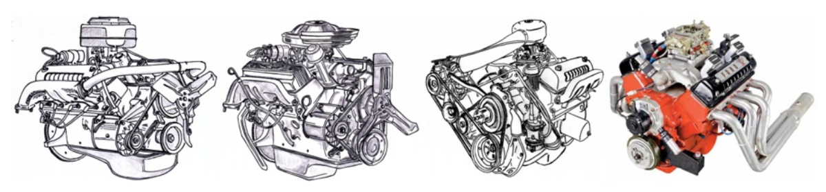
Because pan evacuation or vacuum pumps were not allowed, this permitted me to take advantage of the crankcase breather on the block whereas most blocks do not have this option. I also added two extra breathers to each valve cover to insure that excessive pressure was not a hindrance to piston movement under load. The Engine looks achaic or old school with the original side breather on it though but it was put back on specifically for a performance advantage in this particular instance.
Rules required no modifications to the oil pan. Aftermarket pans were accepted but unfortunately there’s not an off the shelf pan for the Y. Rules also prohibited the use of truck pans or I would have used one of the HD pans I had sitting here. Because modifications to the pan were not allowed, I did get an okay from the rules committee to use a windage tray that sandwiches between the pan and the block. I subsequently built a windage tray that used directional screening and this simply fit in place with a pan gasket on each side of it to seal it in place. One side of the tray acts as a wiper against the crankshaft and rods. If I pull it out of the engine or build another, I’ll get some pictures of it and submit to the Y-Block Magazine. Nothing fancy but every little bit has to help. The oil pump is the gearotor style. I still think there’s a slight advantage to using this style pump over the gear style in both power and pumping even though both are rated the same as far a volume goes. An ARP oil drive keeps it turning.
The Ford Y-Block oiling system is already a ‘side-oiler’ design similar to the later produced 427 FE side-oilers. The main bearings are fed directly from a proprietary oil gallery in the side of the block and then the cam bearings and rocker arms are fed from the mains. Rocker arm oiling for this family of engines is normally by way of a grooved camshaft on the middle journal or a camshaft that is crossdrilled in the center journal which alternately feeds each bank as required. I opted to machine a groove in the block in the center cam journal hole which connects the three holes located there and then this modification is sealed in place with the installed center cam bearing. This provides a solid flow of oil to the heads which I restrict at the rocker arm pedestals with a 0.046″ orifice. The overflow tubes at the ends of the rocker shafts are left intact so that they can free flow which provides ample lubrication for both the distributor gear and the timing chain. This also insures that the rocker shafts are purged of air and that the oil remains cool thus warding off any potential sludging or oil degradation that may occur as a result of stagnation.
Ignition is an MSD distributor using the MSD wires and MSD Digital 6-Plus controller. Sparkplugs are a set of 18mm NOS Autolite BF32’s that I had been saving for a rainy day as these are getting more difficult to find. These plugs have been side gapped and indexed to the individual cylinders. There’s a forthcoming article about how to do this in an upcoming issue of the YBM. Intake manifold is a Blue Thunder unit that’s been simply port matched to the heads. Otherwise it’s stock other than what’s being called the 2nd design manifold. Based on what Gary Burnette has passed on to me, the 2nd design intake flows as well as the 1st design intake after being extrude honed. Carburetion for gasoline is handled by a Holley 750 cfm HP series carb with vacuum secondaries. Backup carb is the 650 cfm Speed Demon carb which has been a proven carb on my Y powered roadster. I lean heavily towards the vacuum secondary carbs due to them being very optimal in flow on a day to day basis as the secondaries only open up as required for a given engine demand. Testing has shown similar results on the Y with both the 650 and 750 cfm carbs and this has to do with the vacuum secondaries simply opening less on the larger carburetor to get the same amount of power output. For E85 fuel, I would simply get a alcohol specific carb in the 650 to 750 range and have to work with it to get the tuneup right.
The tech at the EMC competition ultimately called and said that the Y would not be allowed into the competition with the mushroom tappets. Didn’t matter if it was a factory lifter, rules were specific against mushroom tappets. As a result the engine was not run and instead relegated to the back of the shop. But because I was entered into the competition as an individual and not as an engine choice, I was free to change engines and remain in the competition. As a result, I readied a 427 Tunnel Port engine I had for the competition. Standard bore, factory steel crank, an Isky flat tappet camshaft, a single plane TP intake, MSD ignition, and that engine was ready to be called up. But I was simply too far down on the alternate list to be a player. Do all this again? Not at a number fifteen on the alternate list for sure. Definitely way too much work with not much to show for it and especially with the engine being disallowed due to the original tappet design.
Note that this article was actually a response from Ted to one of the topics I’ve been working up for the “Top Ten Y-Block Stories” for the March-April issue of Legendary Ford Magazine (condensed from this). But the volume and the depth of his response was an article in itself and I know you will enjoy it as much as I did. Shown at the ßbottom-left is the Y-Blocks Forever picture by Jim Culver of Randy Gummelt’s blown 770 HP Y that took the World Y-Block E.T. mark to 8.15 @ 162 mph in Columbus at the 2005 Y-Block Nationals. The motor was prepared by Ted Eaton and Lonnie Putnam – but that’s another one of the expanded “Top Ten” story’s for Bruce’s Y-Block Magazine this year. Bob Martin
Originally published in the Y-Block Magazine, Jan-Feb 2008, Issue #84, A shorter version of the text was published in Legendary Ford Magazine, Mar-Apr 2008 Issue.