When David Church acquired a 1955 Ford Customline two door sedan, it was found that it was originally ordered as a law enforcement car with the P code 292 and a three speed standard transmission. A little back tracking finds that the car was purchased new in North Carolina and when found by David, still had the 1967 North Carolina license plates on it but was now sitting in a South Carolina field. It had been well over 40 years since the car had been last registered and state inspected. Although that car had been sitting in a field for a number of years, a bit of fuel poured into the ‘Teapot’ 4V carburetor and a battery boost gets it started. It drives itself up and onto a trailer for the trip back to Mississippi. The odometer is showing 60K miles but when looking at suspension, pedal wear, and general oil and grease build up at various parts of the car, the assumption is the car has 160K miles instead. More time elapses and now the car is undergoing a complete restoration including an engine rebuild. The engine rebuild is where I come into the picture.
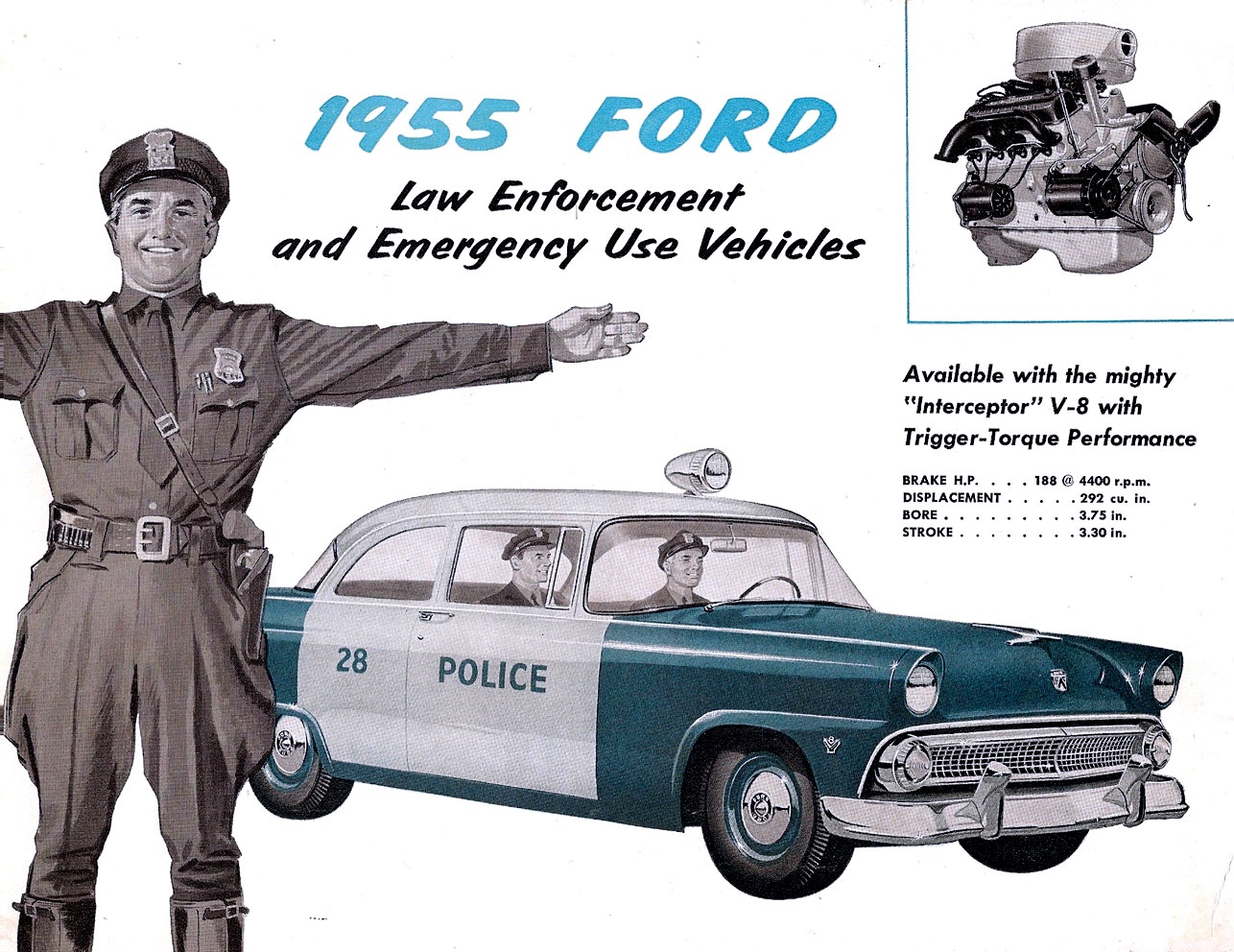
In researching the old sales literature, it’s found that the advertised horsepower for the standard transmission equipped police engine is 188. Looking at some of the other 1955 year model 292 horsepower ratings finds that the Thunderbird standard shift engine is rated at 193HP while the Mercury standard shift engine is rated at 188HP just like the Police engine. Delving deeper into the differences does find that the Thunderbird 292 has 8.1:1 compression ratio versus 7.6:1 for the Police and Mercury engines. Going through the parts manuals does find the Thunderbird engine using the ECL heads while the Police and Mercury standard shift engines uses the ECK head castings. It would appear the only difference between the Ford Police engine and the Mercury engine when equipped with the standard transmission is just the valve covers as both are identical otherwise. The 1955 Ford Police cars using the Mercury engine is no surprise as the 1954 Ford Police cars used the Mercury 256 engine rather than an upgraded 239 version.
Click on pictures for larger images
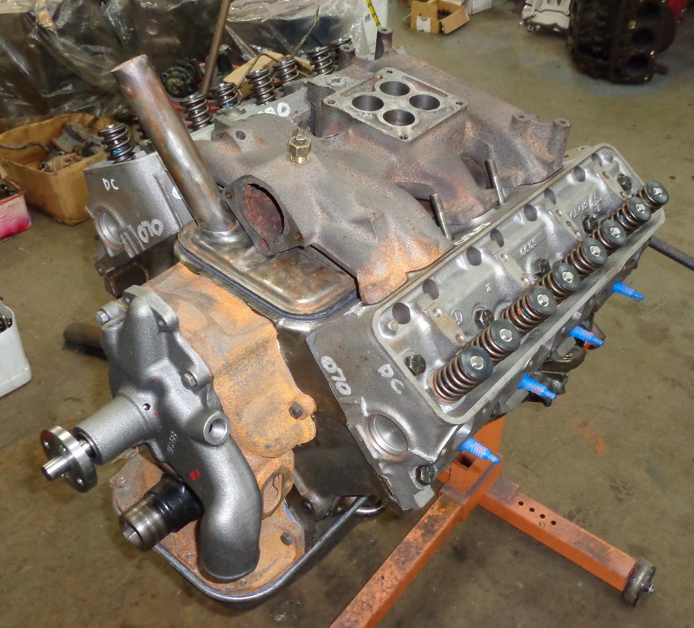
Teardown of this police engine finds that it’s still a standard bore engine with all appearances that the bottom end had never been into before. The block is an ECK casting with a June 4, 1955 casting date while both cylinder heads and the intake manifold have July 6, 1955 casting dates. Deciphering the stamped build date on the front valley cover rail finds the engine being assembled on July 7, 1955 on the third shift. If those dates are correct, there’s obviously no inventory of parts sitting loose for these engines as they are being assembled almost as fast as some of the parts are being cast and machined. The crankshaft journals looked pristine but the rear thrust surface at the center main journal was wasted (badly worn). While the crankshaft could be potentially welded up in that area and re-machined, it was decided to simply replace the crankshaft with another and start fresh. As it works out, another standard journal crankshaft with minimal wear was sourced and used without having to grind the journals undersize.
The ECK-C heads have the 1.78” intake valves which was the intermediate intake valve size for the Y engines. The guides and valves are replaced along with new valve springs and valve locks. The original two piece retainers are replaced with single piece units. There was a problem with the early production Police engines dropping valves when being aggressively driven (over-revved) so there was a service bulletin issued instructing dealers to replace the valve springs on any police engines being brought in for service. Now that more than sixty years has past, the aged valves and especially the exhausts are noted for their propensity in coming apart. With that in mind, retaining the original valves is risky and putting a warranty on the engine if retaining them is out of the question. The desire is for this engine to last at least another sixty years so it’s a no brainer in replacing all the valves. The new valve springs are set up at 76 lbs closed pressure and 230 lbs. pressure at 0.410” valve lift. No port work is being performed simply to keep the engine in a close to ‘as delivered’ state as would have been supplied from Ford originally.

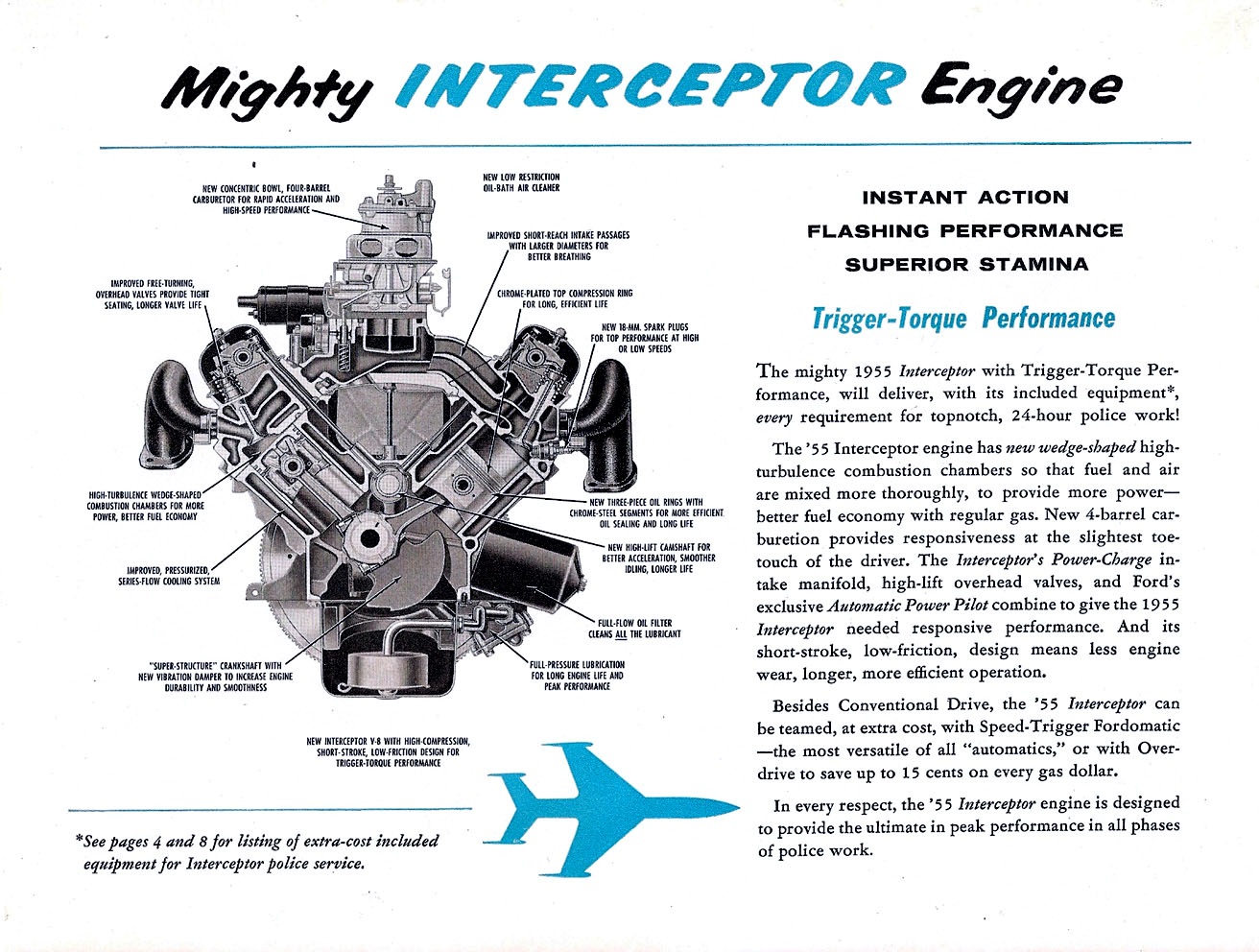
All the combustion chambers are cc’ed and while it’s found that both cylinder heads are similar in chamber volumes, they are very much on the large side in that they are averaging 83.4cc’s. Some reverse engineering finds that the ‘as delivered’ compression ratio was 7.53:1 with the original steel shim head gaskets in place. Before coming across the appropriate sales paperwork and service bulletins, it was initially believed that the engine was suppose to have 8.5:1 compression ratio. Service Bulletin #973 and the sales literature for the Police car option puts this to rest as it states that the standard shift Police 292 was indeed rated at 7.6:1 CR. The automatic transmission equipped 292 Police engines were rated at 198HP and with 8.5:1 CR.
To compound issues with the compression ratio already being to the low side, the wrist pins in the replacement pistons are 0.023” closer to the piston tops and when also taking into account for switching to a composition head gasket rather than the original steel shim style, the compression ratio lowers another full ½ point making it 7.05:1. Zero decking the block only brings the compression ratio back to 7.5:1 so it’s going to take some head milling to get the compression ratio back up to the original advertised 7.6:1. But at this point, the plan does deviate in that the desired compression ratio should at least be what the automatic transmission cars were. To that end, the new target compression ratio is 8.5:1. To attain that, the decks are milled an average of 0.035” to get the pistons level with the decks. The amount of milling required to reduce the chamber volume 1cc on the ECK-C heads is ~0.0056”. A little bit of math indicates that the heads must be milled 0.070” to get the chamber volumes down to 71cc. Internal bracing within the coolant areas of the heads is sufficient enough to permit this amount of milling on these particular heads. To insure that the intake manifold fits correctly, the intake sides of the heads are milled 0.080” which pretty much puts the intake gasket surface parallel with the valve cover rail. As a side note, It’s always recommended to mill the intake side of the heads when possible rather than the intake manifold as this still allows the intake manifold to not be cylinder head specific and can be repurposed later on another set of heads. All this machine work gets the calculated compression ratio back up to 8.5:1.
The block is fresh bored and honed for a replacement set of Silv-O-Lite 0.030” over cast pistons, the mains are align honed, and the decks are fresh machined so that Best Gasket composition head gaskets can be used rather than the original steel shim head gaskets. The piston to wall clearance is 0.0025” when all the machine work is finalized. The pistons are sitting level with the decks at TDC which essentially gives a quench clearance of 0.046” which is the head gasket thickness. The connecting rod big ends are resized with a new set of ARP rod bolts torqued in place while the wrist pin ends get new bronze bushings. With all the block machine work complete, the rotating assembly is dynamically balanced. The bobweight value is 2070 grams and includes the 14 grams used as an oil value.
The camshaft is replaced with a NOS FoMoCo replacement supplied by David Church. It’s still in its original round cardboard tube but the part number is long faded away. The center journal is cross drilled for upper end oiling rather than the grooved journal found on the 1956 and newer replacement camshafts. The specs on this particular camshaft are as follows:
Advertised duration: 231½° Int / 235½° Exh
Lobe lift: 0.256” Int / 0.263” Exh
Calc valve lift: 0.366” Int / 0.376” Exh
Lobe centerline: 112½°
Duration at 0.050”: 196½° Int / 198° Exh
Cam is installed at 111½° Intake lobe C/L
Once the new set of Hy-Lift Johnson lifters are lubed and placed in their respective lifter bores, the pre-lubed camshaft is gently slid into place. The camshaft turns freely within the new bearings so all is well. With the cam retainer bolted in place, the camshaft end play is at 0.006” which is within spec. A note here about lubing the cam and tappets; the moly lube is used only on the lifter faces and camshaft lobes but the shanks of the lifters and cam journals are lubed with a quality engine oil. It’s important that the lifters turn freely in their lifter bores and using oil instead of the moly lube insures this. The moly lube if used on the lifter shanks can actually inhibit lifter rotation which then potentially brings a lifter/lobe failure to the forefront. What happens in the first sixty seconds of running pretty much dictates the ultimate life expectancy of the cam and lifters.
Before installing the Hastings single moly piston rings on the pistons, they are placed and squared within the cylinder bores to check ring end gaps. The replacement rings are not a ‘file to fit’ set but ring end gaps are checked as a safety precaution against being too tight. With some tweaking, the ring end gaps are finalized at 0.018” for the top rings and 0.014” for the second rings. Once this is done, the rings are removed from the individual bores and placed on the pistons going into those particular bores. The rings are installed on the pistons using a ring installing tool rather than twisting them on to the pistons. Using a ring installation tool minimizes the chance for breakage while also eliminates the potential for any ‘twist’ to be imparted into the rings when installing them without the aid of a ring tool.
Short block assembly goes together without any issues. The bearing clearances were previously micrometer checked and it’s verified that the rod bearing clearance is ~0.0015” and main bearing clearance is ~0.0022”. The rod bearing clearances were tightened up by using a std bearing in one half the rod and a 0.001” oversize bearing in the other half. The rod side clearances are checking out at 0.018”-0.025”. As a tip here, when the rod bolts were being torqued to their respective journals, a feeler gauge was being used between the rod pairs to take up all the clearance or ‘slack’. This prevents the rods from twisting during the torquing operation thus preventing the bearing from being unseated and/or sitting crooked within the rod bores.

With the short block together, the camshaft is degreed in and with the stock link timing chain setup, the cam is sitting at 1° advance or at 111½° intake lobe centerline. In keeping with the original intent of having this engine make it’s advertised horsepower rating, the camshaft is left at 1° advance rather than broaching a new keyway slot in either the cam gear or crank gear in which to further advance the cam timing. While advancing the camshaft in this particular case would help low end grunt and idle, it would be counter-productive to making the rated horsepower ratings. At the conclusion of degreeing in the camshaft, the crankshaft is rotated to put the #1 piston back on TDC before removing the degree wheel. The timing cover, timing pointer, and damper are then installed to insure that the TDC on the damper is aligned accurately to the pointer. Any discrepancies between the two are taken care of by simply bending the pointer accordingly in which to compensate. The damper (freshly rebuilt by Damper Doctor) is then removed so that the remainder of the engine can be assembled and painted. The damper is to remain flat black so it’s off the engine when the remainder of the engine is painted with high heat primer and then final coated with Bill Hirsch Ford ‘T-Bird’ Red. A little bit too orange for my taste but it is the right shade of Ford Red for this application. After engine painting is complete, the damper is reinstalled.
It’s now just a matter of taking care of the little details before installing the engine on the dyno. Some of those details include checking out the Load-O-Matic distributor with its new breaker points and related parts, new spark plugs and wires, replacement wire looms, the addition of six quarts of Valvoline 10W-40 conventional grade oil, and a Wix 51515 oil filter. The original cartridge oil filter goes to the wayside and is replaced with the newer spin on style. In this case, some items simply don’t need to remain original. A 4oz bottle of ZDDPlus is added to the crankcase as additional insurance that the Zinc/Phosphorus amounts are sufficient for break in. Before installing the distributor, the engine is pre-lubed to guarantee that oil has filled the oil filter and various passages as well as having adequate cranking oil pressure. The original List #1074-1 Holley Teapot 4V carburetor looks clean and usable so it’s not taken apart at this point and is installed on the intake along with the original ½” phenolic carb spacer. Fuel in poured into the top vent hole in the carb so that the fuel pump does not have to work at filling the carb when attempting the first start of the engine.
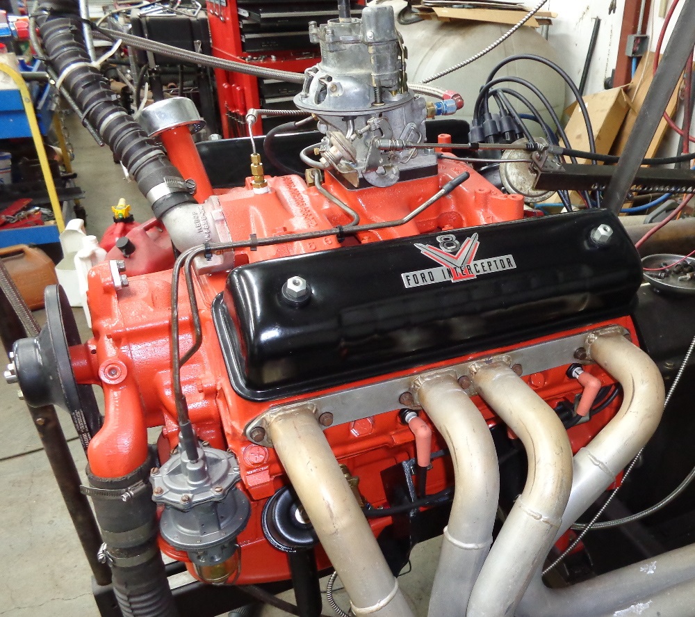
With the engine on the dyno, it starts up immediately without any fanfare and is brought up to a fast idle for both the camshaft and piston ring break in. The engine is being run with a set of headers instead of exhaust manifolds as this provides a more accurate way to monitor the air fuel mixtures. While the camshaft is being broken in, the engine is repeatedly being loaded and unloaded against the dyno water brake so that the piston rings can seat in much more quickly. After allowing the engine to completely cool in which to put a completed heat cycle in the engine, it’s then restarted for some power testing.
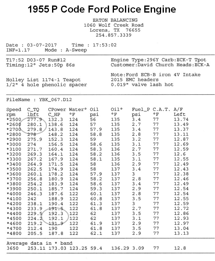
The first series of dyno pulls nets a best of 181HP and 266 TQ. The original List #1074-1 Teapot carb is being troublesome with the accelerator pump having a weak shot and the numbers are down from what was expected so the carb is changed out to a List #1164-2 carb off of a 1956 Thunderbird with a 312 engine. The Thunderbird carb had been freshly kitted and with it installed on the engine, it makes a clean pull netting 191HP/267TQ. The original ECK-T 1074-1 carb is then disassembled, cleaned, and rebuilt using a Daytona Carb Parts #603 ethanol friendly carburetor kit. With the rebuilt carb reinstalled on the engine, the engine is now responsive when winging the throttle with no hesitation or dead spot. The dyno likes it too with 192HP/280TQ numbers coming to the forefront. The carb jets remain stock as 50’s in the primaries and 86’s in the secondary sides. The engine is making its best power numbers and idles well with the Load-O-Matic distributor set at 12° initial timing and the valves set at 0.019” hot. At this point, the engine comes off the dyno and is ready for reassembly back into the chassis.
While a horsepower rating of 188 doesn’t sound like much by today’s standards, this was a serious performer back when it was new. This engine was just the precursor of things to come as the following year started seeing larger valves and experimentation with more aggressive camshaft grinds.
All for now and until next issue, Happy Y Motoring. Ted Eaton.
Originally published in The Y-Block Magazine, Issue #147, July-August 2018