Although there were a multitude of Ford 272 Y-Block engines used in both cars and trucks, they are pretty much disregarded as the basis for a high performance build and for that matter, as a replacement engine when a 292 or 312 is available instead. While building a high performance 272 Y has been on the ‘like to do’ list for awhile, it has been a hard sell when the larger Y engines simply make those higher power numbers much easier to come by. That all changed recently when a customer wanted to use the original 272 block from their 1956 Ford pickup as the basis for a new engine in that same truck. In this instance, they wanted modern performance upgrades applied to it including a pair of Mummert aluminum heads.

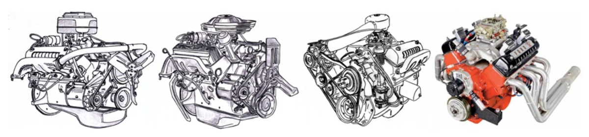
Stock 272 with two barrel carb and single exhaust system.
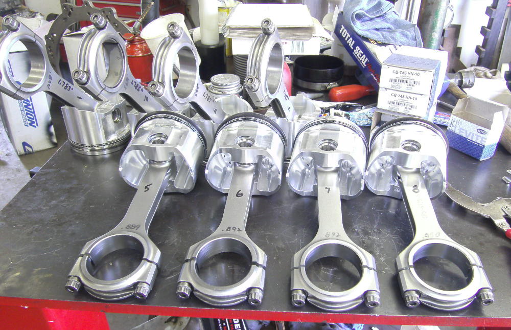
The block itself was still a standard bore and in finding that 1.2mm compression rings were available for a 3.658” bore, the block was bored so it was essentially 0.033” over the stock bore size. While the new compression rings dropped in width from the stock 5/32” (0.156”) widths to 1.2mm (0.047”), the oil rings reduce from the stock 3/16” (0.188”) widths to 3.0mm (0.118”). The 272 crankshaft was still std/std on the journals and was subsequently reground so it was 0.010” undersize on the mains. The rod journals were offset ground which increased the stroke from 3.3” to 3.48”. The new rod journal diameter is now 2.000” where it had been 2.188”. This necessitated the use of new connecting rods which is where a set of Eagle 6.125” long H-Beam rods come into play. These do use a 0.927” diameter wrist pin versus the stock pin diameter of 0.912”. Although the rod journals were slightly widened to a 1.810” dimension during the grinding operation, they were still not wide enough to accommodate the out of the box H-Beam rods being used. The new rods were narrowed to fit accordingly as further widening the rod journals would increase the possibility for the oil holes being exposed in the journal filets. Narrower than stock rod bearings were available and these did not require any modifications. The stroke change along with the metric rings and larger wrist pin diameter called for a custom piston set which was supplied by Diamond Pistons. These have a 1.885” compression height versus the 1.760”-1.777” that is found in the stock replacement 272 and 292 pistons. Once all the rotating parts were assembled and dry fitted, the rotating assembly along with the flywheel, clutch disk, and pressure plate assembly were precision balanced. The balancing bob-weight value for the rotating assembly is 1606 grams which is considerably lighter than stock. The final cubic inch for this combination ends up being 293 with the static compression ratio calculating to be 9.7:1 with the pistons sitting 0.005” above the deck and using Best Gasket head gaskets with 10.0cc combustion volumes.
Click on picture for larger image.
Oil modifications include adding a groove in the center cam journal hole of the block. This allows oil to flow behind the cam bearing to interconnect the three holes located there and eliminates the possibility that the oil flow to the top end will be restricted by a worn cam bearing in the future. The oil filter adapter also has an additional pair of 5/16” holes added alongside the slot that already resides there to insure an adequate flow of oil to the filter. The oil pump itself is a rebuilt gerotor style of oil pump. The oil pan is the original rear sump pan but has a pair of baffles added to prevent the oil from moving or sloshing forward under braking conditions.

Click on picture for larger image.
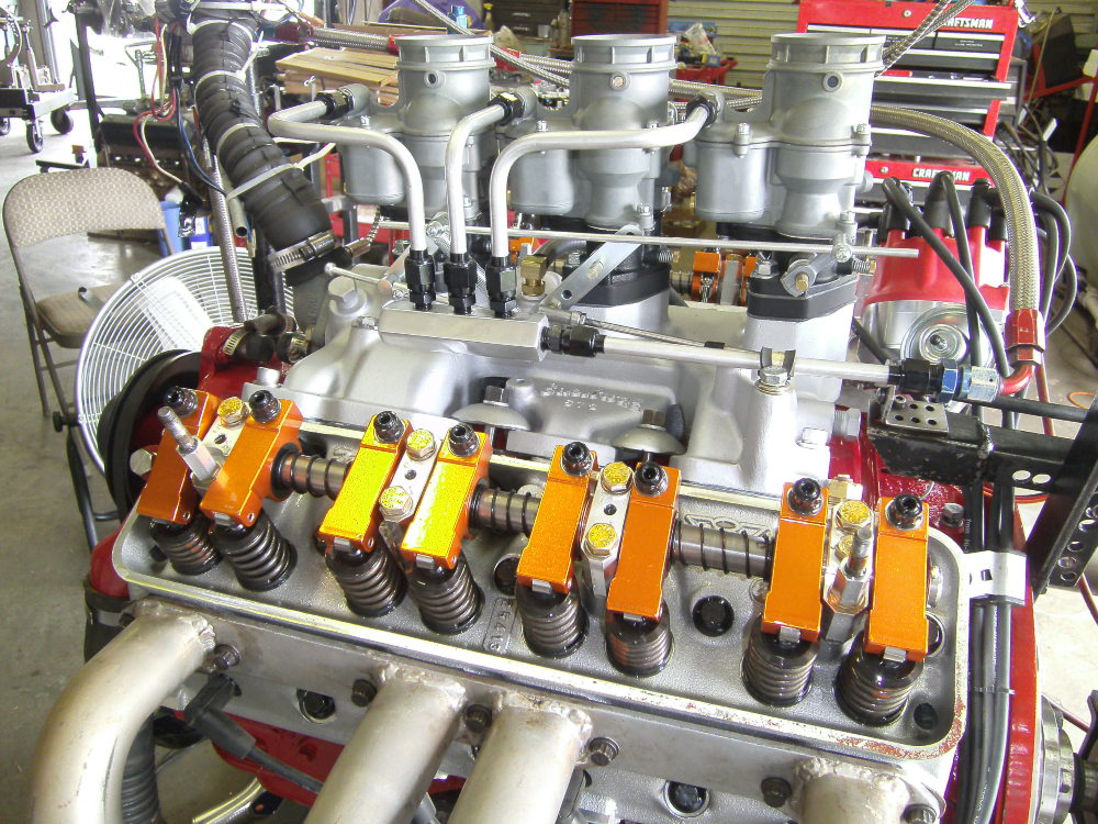
An ‘angry’ sounding camshaft was requested so a new Isky grind was developed for this combination. This grind started out using the Seventies era Crower Monarch camshaft as a starting point. That older Crower grind has been used successfully in the dyno mule but with new lobe profiles being available, this new grind does have more aggressive ramps on the lobes thus providing more net valve lift while also reducing the advertised duration numbers. The ‘as ground’ lobe centers are also reduced a couple of degrees to give a choppier idle. The new Isky camshaft is a symmetrical grind where both the intake and exhaust lobes are the same. Advertised duration is 272°, the 0.050” duration is 238°, the lobes are ground on 108° centers, and the lobe lift is 0.320”. The camshaft is installed in the engine at 4° of crankshaft advance or at 104° intake lobe centerline. Harland Sharp 1.6:1 roller rockers are being used which puts the lift at the valve before valve lash is taken into account at 0.512”. The shaft to rocker clearance is set at 0.002” which allows the overflow tubes to be eliminated and oiling to the rockers is now pressurized. Completing the list of valve train parts are Hylift Johnson tappets and Smith Brothers 8.100” effective length pushrods.
Click on picture for larger image.
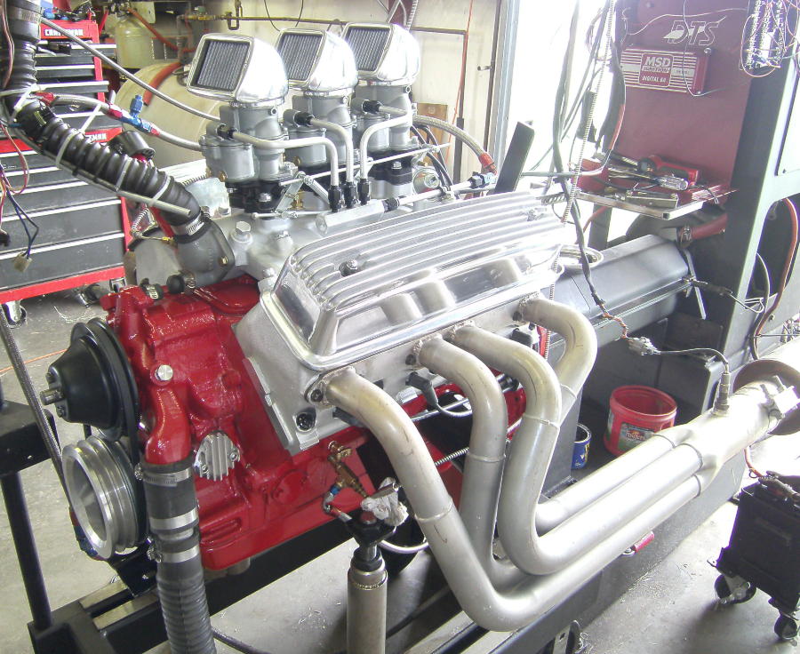
The cylinder heads are the Mummert aluminum heads. These have had sanding rolls taken to the ports and bowls for a simple cleanup with emphasis being placed on not making the ports any larger. Other than this mod, the heads are used as delivered. ARP head bolts fasten the heads to the block while Best Gaskets are used throughout the engine to seal it up. The intake manifold selected for this build is an older Edelbrock #573 three deuce manifold topped off with three new Edelbrock 94 carburetors. Linkages are progressive where the center carburetor is about 2/3 open before the end carbs start opening. A PCV valve system is also added which allowed the original road draft tube hole in the side of the block to be blocked off. The PCV valve itself is located in the valley cover using a rubber grommet to hold the valve in place.

PCV Valve hookup. Click on picture for larger image.
Once engine assembly is complete, the engine is prepared for running on the dyno. The crankcase gets six quarts of API-SN Valvoline 10W-40 conventional oil along with a Wix 51515 oil filter. After pre-lubing the engine, the MSD #8383 billet distributor is installed. The distributor is set up with the blue bushing (21°) and with the light silver and light blue springs so that the mechanical advance curve is all in by 3200 rpms. The engine is started up and ran at the prerequisite 2000-2500 rpms for twenty minutes and during this time, the engine is repeatedly put under a load to speed up the piston ring break-in. Once the engine has been ‘run in’ the valve train is checked for any problems and a ‘hot’ valve lash adjustment is performed. After resetting the valve lash so it is at 0.024” in hot conditions, the engine is restarted and brought up to 3200 rpms where the total ignition timing is set at 37° BTDC. No problems are found so all is good to go for general carburetor tune up and dyno testing. When attempting to get the engine to idle at a reasonable low speed, it would not continue to run at anything less than 1300-1400 rpms. It was first thought that a serious vacuum leak was the culprit but re-examining all the different gaskets and seals found no problems. Inserting some wires into the idle feed restrictions within all three carburetors did help so a phone call to Edelbrock had me taking a different approach. In talking to the Edelbrock technician, the camshaft is just a bit wild for these carbs and as such, the carburetor signal is reduced which in turn is making the idle circuit too lean. The fuel atomization nozzles were removed from each carburetor and the idle feed restrictions are reduced in size from 0.063” to 0.052” which in turn fixes the lean condition in the idle circuits. The engine can now idle down to 750 rpms without any obnoxious fuel smells which would have indicated being too rich. As a matter of reference, all three carbs have idle circuits and power valves.
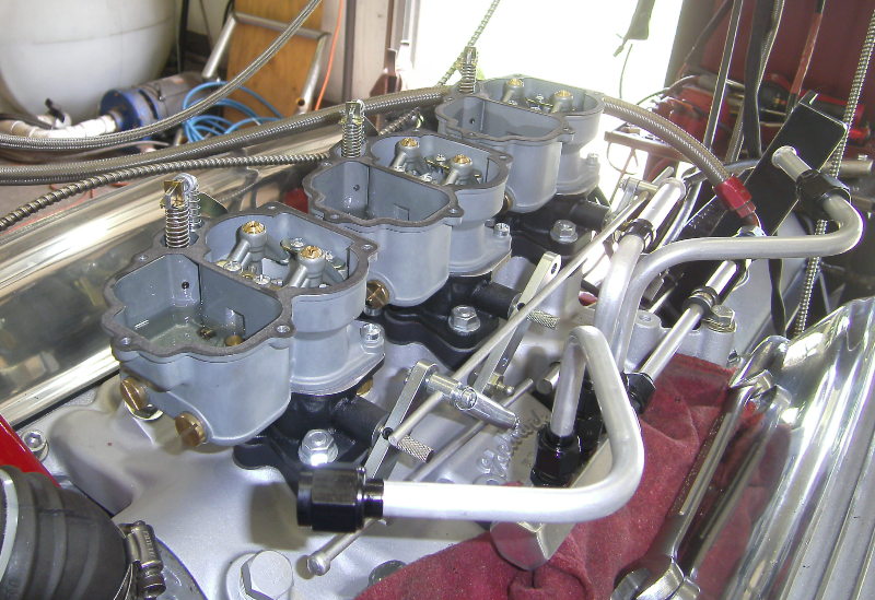
Carb tops are off to modify air bleeds.
Click on picture for larger image.
The engine was dynoed both before and after the carburetor modifications and it was noted that full throttle performance was not affected by the carburetor modifications. Torque values are stout throughout the rpm band and the horsepower numbers peak at 355 at 6100 rpms. The torque peaks out at 331 lbs/ft at 4800 rpms but averages 321 lbs/ft from 3100 to 6400 rpms. This engine has a very flat torque curve which makes it a work horse at any rpm. The dyno sheet is included at the end of this article.

Click on pictures for larger images.
So there you have it. The 272 can be worked over so it’s a power house just like its 292 and 312 big brothers. While there’s no definitive data to state otherwise, the smaller cubes with this combination should actually be more fuel efficient in the long haul than that which is experienced with the larger engines. That is assuming one can drive this with a light touch on the accelerator pedal and not be tempted to continually test the acceleration capabilities. Until next time, Happy Y motoring. Ted Eaton.
This article was previously published in the Y-Block Magazine, July-August 2014, Issue #123, Vol 21, No. 4