A unique feature with the shaft mounted rocker arms such as those found on the Y-Block (as well as the FE, MEL, and LYB) Ford engines is that the solid lifter or lash adjusting versions can be measurably variable in the rocker arm ratio depending upon where the lash adjusting screw is positioned within its range of travel. Where changing the pushrod length on the stud mounted or trunion type of rocker arm affects the geometry of the rocker and not the rocker arm ratio, changing the pushrod length on the shaft mounted Y-Block rocker allows for some deviation from the advertised amount of rocker arm ratio. This in turn allows some flexibility in rocker arm ratio tuning without having to purchase specific rockers for this purpose. What makes this possible is that the contact point for the pushrod at the bottom of the adjustment screw changes in relationship to the center of the pivot point (shaft) as the adjusting screw is moved up or down. (see illustration)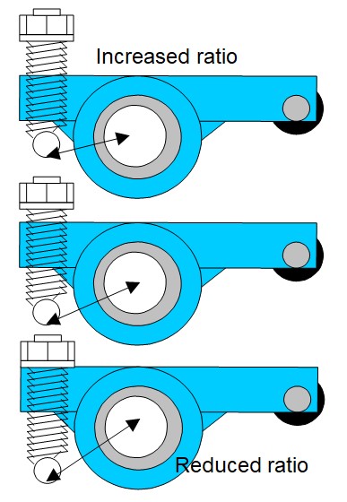
Depending upon the year model, Y’s can be found with rocker arms that have an advertised ratio of 1.43:1 or 1.54:1. Measurements performed on these rockers shows that the advertised ratio is more closely achieved when the adjusting screws are approximately half way down or midpoint in their adjustment travel. When the rocker adjusting screws are taken towards their extreme ends of adjustment, then the ratios do deviate from this advertised value. This same phenomenon is also seen on the aftermarket roller rockers that are available for the Y.
This rocker ratio variability can be measured several different ways. In the past, I have used an adjustable length pushrod so that the rocker adjustment screw could be varied and then measuring the net lift at the valve while maintaining zero lash. With the cam lobe lift being known, it’s just a simple matter of dividing the lift at the valve by the cam lobe lift to obtain the real time rocker arm ratio. This particular measurement is performed after achieving optimum rocker arm geometry which is effectively done by altering the rocker stand heights. Rocker arm geometry will also affect the net valve lift if the rocker shafts themselves are not at their optimum height. This has been covered in detail in a separate technical article.
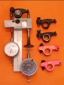
To facilitate an easier method of rocker arm ratio measurements, a simple fixture with two dial indicators was fabricated that would simulate the rocker as mounted on a head. This would facilitate much quicker back to back testing of the different rocker arms without having to dry assemble the rockers on a workable head in order to simulate their movement through the various scenarios. Based on measurements taken on several different rocker arms, some trends in the observations become apparent. If the adjuster is at the top of its adjustment range, then an increase in rocker ratio would be observed. Conversely, if the adjuster is at the bottom of its range or screwed all the way in, then there would be decrease in rocker ratio. The following chart summarizes the measurements and are converted to rocker arm ratio values.
| Adjuster down all the way. | Adjuster at the mid point position. | Adjuster at the top of its travel. | |
| 1.43:1 Y Rocker | 1.370 | 1.425 | 1.472 |
| 1.54:1 Y Rocker | 1.438 | 1.500 | 1.560 |
| 1.6:1 Dove Rckr | 1.528 | 1.599 | 1.670 |
Having the ability to change to different rocker ratios opens up more tuning options regarding performance and/or efficiency of an engine. There are instances where it would be ideal to either increase or reduce the rocker ratio on either or both valves depending upon the camshaft and the specific application that the engine is being used. This myriad of combinations would be another chapter in itself so that will be left for another day. What must be remembered at this time is that the net valve lift is greatly affected by changes in rocker ratio as well as the speed in which the valve is being lifted from its seat. As an example for a particular scenario, I’ll use the Isky T-505 camshaft for the Y which has an advertised valve lift of 0.505”. This is calculated using a 1.5:1 rocker and if a 1.43 rocker is utilized, then this lift drops to a nominal 0.481” lift and reduces even further to 0.461” if the pushrod is shortened as much as possible. On the other side of the spectrum are the aftermarket 1.6 rockers for the Y which would allow the gross valve lift on this same camshaft to increase to 0.539” lift and if the pushrod is lengthened as much as the rocker adjustment will tolerate, then 0.562” lift. The valve lash would be subtracted from all these equations for actual lift at the valve.
This range in rocker arm variability does create some interesting scenarios that can keep an engine from running at its peak potential or become a potential source for breakage or engine damage. An example is an engine that has one head milled more than the other but has not had the pushrods adjusted appropriately in which to compensate can effectively be running different rocker arm ratios from side to side. And yet another instance is where mismatched heads from different years are on the same engine with a subsequent different height of the rocker shafts on each side. Although either of these scenarios could be checked by just visibly insuring that the rocker arm adjustment screws are sitting in approximately the same location on both banks of rockers, it is advisable to do an actual check of the net valve lifts at the valves. Milling the heads to increase the compression ratio also effectively increases the rocker arm ratio in that the adjustment screws must be moved up in order to use the same length pushrods. In this particular case, if the valve to piston clearance was already marginal then the valve is automatically positioned closer to the piston by the amount the head was milled. What compounds this is that the rocker ratio also increased if the same length pushrods are retained which effectively puts more lift at the valve which left unchecked could ultimately be just the amount that allows the valve to contact the piston.
As always, I hope this topic did not thoroughly confuse you but instead did help to enlighten you on just another nuance with these engines.
Until next time, Happy Motoring. Ted Eaton.
Originally published in the Y-Block Magazine, Nov-Dec 2005, Issue #71.