“An Introduction to Engine Balancing”
By Ted Eaton
Although the terms “blueprinted and balanced” are typically synonymous with any kind of performance buildup of an engine, it must be noted is that these two terms are completely different in relation to their perceived functions and are generally performed independently of each other.
Whereas “blueprint” specifically targets an engines fits, tolerances, volumes, and/or settings, the “balance” deals with the physics of achieving a rotating mass that is the most conducive to transmitting as much potential power as possible to an engines flywheel rather than having it wasted within the confines of the block. By eliminating power robbing vibration or harmonics that can be caused by a state of out of balance, power or torque that would normally be dissipated through an engines main bearings and into the block can instead be redirected to the drive end of the crankshaft proportionally by the degree to which the rotating mass is balanced. Simply stated, the better the balance, the more the potential power that can be seen at the flywheel. For the driver of a vehicle with a balanced engine, it’s simply a physically smoother running engine with improved acceleration.
The physics of balancing can be broken down into two types of imbalance, static and dynamic. 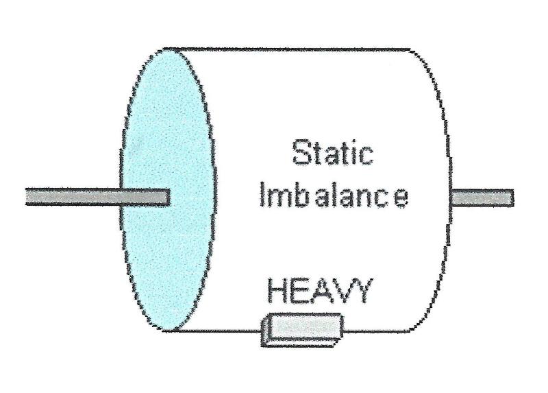 Static imbalance will manifest itself as a maximum amount of out of balance in a single area or plane along the outer most surface of a rotating axis. On the other hand, a rotating part can be in a perfect state of static balance but can be off significantly when examining its dynamic balance.
 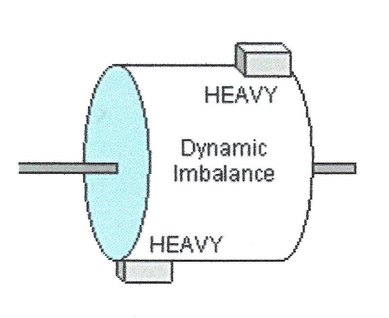 If a vibration is observed, static imbalance is the force most likely being felt but dynamic out of balance can also be present depending upon the rotating mass’s length. Even when physical vibration is not being felt, dynamic imbalance can be present in severe enough degrees to be quite destructive or power robbing although no shake or vibration is physically evident. Static out of balance can be found in any rotating part regardless of the length along its rotating axis but dynamic out of balance becomes more significant as rotating pieces increase in length along its rotating axis. Very narrow rotating parts such as flywheels will not exhibit much in the way of dynamic out of balance but can be good examples of static imbalance. A longer item like a crankshaft may not show evidence of being out of balance statically but can be off significantly when looking at its dynamic aspects.
Over the years, set rules or best practices for engine balancing have been established for the various engine designs. These practices at their best are a compromise dealing with conflicting forces that try to share the same physical space normally defined as either rotating or reciprocating mass. While rotating mass can be described as that which travels only in a circular motion such as the crankshaft or the connecting rod big ends, reciprocating mass would be those components that are attached to the crankshaft but travel in a predefined non-circular motion such as the pistons or the connecting rod small ends. Getting back to conflicting forces, the connecting rod does not have a distinct line separating the reciprocating mass from the rotating mass due to the fact that the area of the rod between the wrist pin and the crank pin exhibits the traits of both reciprocating and rotating mass. As this in-between area gets closer to the crank pin, it exhibits more rotating mass characteristics than reciprocating; likewise, as this same area gets closer to the wrist pin, it exhibits more reciprocating mass characteristics than rotating. For this reason, the longer the rod and/or the cranks stroke, then the more this ambiguity. This ambiguity and how to compensate for it will be discussed in a later article in this series.
To precision balance an engine, all pieces of the rotating assembly must be considered. A list of these parts will include the crankshaft, harmonic damper or front hub, flywheel, the clutch disk and pressure plate if a manual shift transmission is being used, connecting rods, pistons with their pins and respective locks, compression and oil rings, rod bearings, and the lower timing gear. Basically everything that moves or rotates as part of the engine assembly short of the camshaft and its attached gear. Also worth considering are the belt pulleys and their retaining bolts. All machine work or modifications including rod reconditioning, piston dome or valve relief machining, and general deburring or polishing of any of the internal engine parts must have been already performed prior to having the assembly balanced as doing so after the fact will only nullify the effects of having the rotating assembly precision balanced.
When taking all the necessary parts to your favorite shop for balancing, it’s important to note that the connecting rods or the piston rings must not yet be installed on the pistons. Likewise, the rod bearings do not need to be installed in the rods or the rods installed on the crankshaft. Because the rods must be balanced end for end separately, they are required to be independent or apart from the pistons. Although the rings could technically be on the pistons during the balancing procedure, they also need to remain uninstalled in order to insure that no machining chips are caught in the ring lands during any of the weight reduction operations being performed.
The balancing operation as performed by your machine shop can be separated into two basic operations; weighing and/or match weighing the various components and then spin balancing the crankshaft itself. Depending upon an engines design, there may be a specific order in which these operations are performed. Most engines with opposed or inline cylinders (i.e.. 4 & 6 cylinders) normally do not require a bobweight to be attached to the crankshaft rod journals prior to spin balancing in order to simulate any of the component pieces (rods, pistons, etc.) that are normally attached to the crankshaft assembly. This is due to the nature of the physical forces being applied at equally spaced intervals on these engines and subsequently being equally opposed or counteracting. A “V” type cylinder engine on the other hand does not have these forces being applied at the same opposing intervals and depending upon the angle between the opposing cylinders, does require a bob weight installed on each crank pin for balancing purposes that uses 100% of the rotating mass but only a fraction or a percentage of the reciprocating mass for each piston/rod assembly. A 90° V design, which covers a majority of the common V8 engines, requires a bobweight on each crankpin during balancing that represents not only 100% of the rotating mass but also a standard value of 50% representing the reciprocating mass. Even this standard reciprocating factor is subject to change for a 90° V design engine in special circumstances. More on that in a later article in this series.
There are some of the balancing operations that can be performed by the novice in his own shop but the spinning of the crankshaft is best done by those with the appropriate equipment and experience. If so inclined and with a nominal purchase in equipment and materials to do so, the pistons and connecting rods can be independently weighed and appropriately lightened by the enthusiast before sending the crankshaft out to be balanced. A scale reading in grams along with a connecting rod holding fixture that can separate the big end and small end weights would be the bare minimum equipment requirements. Then it’s just a simple matter of finding the lightest piston, lightest reciprocating rod end weight, and lightest rotating end weight and making the remaining component pieces match these weights. The equipment used for lightening operations would be wholly dependent upon the quality of the machining that’s being targeted for as well as the initial design of the pieces that must be lightened. Some parts may require special tools or tooling for machining in order to keep from sacrificing or minimizing the strength of the piece being lightened. For those of you that have a grinder, belt sander, drill press, and/or some form of milling machine available, most lightening operations would be well within your reach. Look for more detail on this in the subsequent articles.
These series of articles are hoped to heighten your awareness of how precision balancing not only increases engine efficiency, but ultimately also increases engine life through reduced internal vibration and unwarranted stress. The next article in this series will cover in detail the differences between external and internal balance. Until then, happy motoring.
Originally published in Y-Block Magazine, Jul-Aug 2004, Vol 11, No. 4, Issue #63