It boggles the mind as to how many 1954 Ford and Mercury cars and pickups are still out there running with their original 239 and 256 engines. But with it now being over seventy years since those engines were introduced, the need for parts and/or the rebuilding of those engines does become necessary even for those that are not driven much each year. While some of those 1954 Ford vehicles have been upgraded to a later model Y engine, there’s still a significant number of them out there still running the original engines. I normally shy away from rebuilding the 1954 Y engines due to the scarcity of some of the 1954 only parts that are on those engines. Some of those parts includes the camshaft, camshaft bearings, oil pumps, water pumps, and fuel pumps.
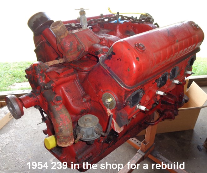
But my arm is twisted and I take on this particular 239 build. In this instance, the customer would like to rebuild the original engine just for purposes of retaining the original block and heads. And I do like the idea of recycling parts that are rebuildable. This 239 comes from a 1954 Ford F100 pickup and arrives into the shop with complaints of being lack luster in performance and in need of a rebuild. While this engine has been previously rebuilt at least once before and possibly twice, it is again well worn and in need of another rebuild. The customer would also like the original rated power levels increased and provides a 1954 Mercury 256 four-barrel intake to be installed on the engine during the freshening up process.
A tear down of the engine finds that the cylinders are already a well-worn 0.040” over and the crankshaft journals are now at 0.030” and 0.040” undersize. With the scarcity of 0.040” or more undersize bearings, this engine presents an opportunity to install a later model crankshaft with more stroke to make for a quick increase in both the cubic inches and the compression ratio. An 0.080” overbore is found to clean up the existing bores and a quick check of the cylinder wall thickness finds that the remaining wall thickness will be more than adequate for this build.
Rather than use an original 3.1” stroke crankshaft, the plan is to go with a 312 crankshaft (3.44″ stroke) with the mains cut down to the 292 standard main size. A quick combustion chamber measurement of the original heads and some even quicker math indicates that the compression ratio with a 312 crankshaft and zero deck will still be shy of 8:1. With a new set of custom metric ringed pistons in hand, the block is bored and after being torque plate honed, the final cylinder size is 3.580”. After mocking up the engine with the piston and connecting rod assemblies, the decks are machined ~0.015” for a zero deck clearance for the pistons.
Using a 312 crankshaft will mandate using a connecting rod with a shorter bolt design and there are three oem rods that fits that requirement; those are the 6.252” 312 ECZ and 292 C1TE truck rods and the longer 6.324” 292 C2AE rods. The longer C2AE rods are selected for this build which pushes the wrist pin in the piston ~0.072” closer to the piston top versus using the shorter ECZ or C1TE rods. The compression height (wrist pin location) on the new pistons is 1.712” versus 1.875” on the original pistons. To go along with the shorter length rod bolts, the camshaft will also need to be upgraded to the smaller journal 1955 and up camshaft so that the connecting rods will clear the cam lobes. If using an original big journal camshaft with anything other than the original 3.1” stroke crankshaft, then connecting rod to camshaft interference comes to the forefront. The combination of small journal camshaft, short length bolt connecting rods, a 312 crankshaft, and an 0.080” overbore for the EBU-E block is a doable combination for this engine and will make for 277 cubic inches when finished.
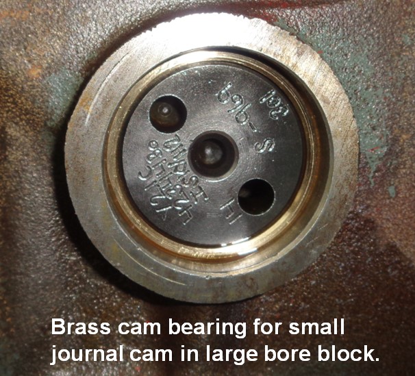
Because the original large journal camshaft is being replaced with a later model smaller journal camshaft, the cam bearings must be fabricated from scratch. These are made from bearing brass and are machined for a 0.002” press fit into the block. There is some variance in the hole sizes within the cam bores in the block and that requires that each bearing is made specifically for each cam bore hole. Where I would normally put a groove in the center cam bore of the block to redirect the oil to the top end, in this instance I did put the groove on the outer O.D. of the new bearing for the top end oil. The new bearings being ~1/8” thick permitted this. The replacement camshaft has a grooved center journal versus the original camshaft being cross-drilled but with the cam bearing now being grooved on its outer diameter, only one oil hole is put in the center bearing. The groove at the center camshaft journal no longer provides any additional oiling to the top end of the engine. To eliminate the possibility of too much oil to the top end, 0.078” restrictors are installed in the appropriate stand at the bottom of each rocker arm assembly.
With the change in camshaft, the distributor is also being upgraded. The original Load-O-Matic distributor with its 13 tooth gear is being upgraded to a modern electronic billet distributor with a 14 tooth gear. That distributor change also requires a ¼” hex drive oil pump and a corresponding intermediate oil shaft. An ARP oil pump drive is being used as those are now the same price as the replacement oil drives; the ARP unit is definitely a heavier duty piece. Had it been desired to retain the original L-O-M distributor, then it would have been necessary to replace the original 13 tooth gear with the later model 14 tooth gear. In that instance, the original slotted oil pump drive and slotted tang oil pump could have been retained. Another option would have been to use a 1957 and up Y distributor but that would have required the subsequent oil drive and oil pump change as well.
The rotating assembly consisting of the freshly machined 312 crankshaft, connecting rods freshly resized with new ARP bolts, custom Diamond pistons and metric rings, and bearings is electronically balanced. The bobweight value for this new combination is 1860 grams versus the stock bobweight value being in the neighborhood of 2000 grams. That lighter rotating assembly will allow the engine to accelerate quicker in the vehicle as well as remove some of the stress that was originally present at both the connecting rod bearings and bolts.
The stock EBU-6015-F cylinder heads are treated to a fresh valve job. They are checked for straightness and found to be okay thus not requiring any milling. Checking the square pads under the exhaust ports finds those pads at ~1.005” suggesting that this set of heads have never been milled. Of note here is that the 1954 engines use a washered 14mm spark plug versus all newer oem Ford Y-Block heads using 18mm tapered seat spark plugs. Also worth noting is that the ’54 heads are specific to the ’54 blocks and the head gaskets are also specific to the ’54 engines. The ’54 head gaskets are not suitable for the later model engines due to both the bore and coolant hole locations being different.
The original 1.43:1 rocker arm assemblies have the locking nut adjusters and are disassembled and cleaned. The rocker arm tips are machined so that they have fresh valve stem contacting pads. With new rocker shafts in hand, the assemblies are reassembled. The original rocker arm overflow tubes are retained in lieu of pressurizing the rocker arm assemblies. As mentioned earlier, 0.078” restrictors are installed in each assembly to help control the amount of oil going to the top end of the engine. The factory oil restriction at the center cam bearing has been eliminated and with the addition of the groove on the outer side of the center cam bearing, there will now be an excess of oil to the top end if not using the added restrictors.

ARP grade eight head bolts are used in lieu of the factory grade 5/6 bolts.
The short block assembly goes together without any hiccups. The Hy-Lift Johnson tappets are installed first and then the camshaft. A custom ground Isky camshaft is selected and is a replacement for the 1957 V8 camshafts. The specs are as follows:
238° – Advertised duration
208° – Duration at 0.050”
0.284”– Lobe lift
0.406” – Calculated total lift at valve
112° – As ground lobe centerline
107° – Installed intake lobe centerline
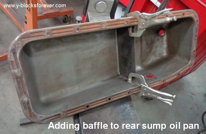
A neoprene real main seal is used in lieu of using an original type rope seal. The six quarts with filter rear sump oil pan is modified with the addition of a baffle to prevent oil starvation during heavy braking. The timing cover is upgraded to a newer version which will accommodate the ’55 and newer water pump and fuel pump.
The heads are bolted to the engine with a new set of grade eight ARP bolts which are torqued to 75 lbs/ft for the short bolts and 80 lbs/ft for the longer bolts. Whereas the original grade five top row of bolts were all the same lengths, the new set of bolts are of two different lengths for the top row with the end bolts being slightly longer than the three center bolts. The new ARP head bolts use hardened washers versus the original bolts not using any washers. Best Gasket head gaskets specific to the 1954 engines are used and these are 0.045” thick versus the original steel shim gaskets being 0.025” thick. But with the addition of the grade eight head bolts and the composite head gaskets, a retorque of the head bolts after the engine has been fired up will not be required.
The rocker arm assemblies are bolted to the cylinder heads and when using the original pushrods, it’s found that they are on the short side when using the original oil deflection trays under the rocker arms. The original pushrods have an effective length of 7.975” and are changed out to the ’57 version pushrods which are 8.100” in effective length. The smaller base circle on the new camshaft along with using the valve train oil trays explains why the longer pushrods are required. In the grand scheme of things, the pushrods could have been another 0.100” longer and been even better suited to this application but what is already being used will be okay. This engine is to be a daily runner and getting every iota of performance out of it is not a priority.
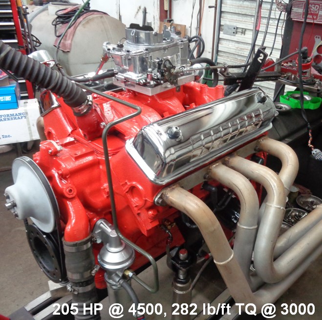
The original two-barrel intake manifold goes to the way side and is replaced by the provided 1954 Mercury 256 four barrel EBY-D intake manifold. The four holes at the carburetor base of the manifold are machined so that they are two ovals. This is similar to the modification that is performed on the later model ECZ-B 4V iron intake manifolds as it does help to increase the air flow within the manifold. A machined adapter on top of this will allow a more modern four-barrel carburetor to be used. In this particular instance, a Summit 500 cfm carburetor is selected. A Carter M4008 mechanical fuel pump for a 390 Ford is being used to supply the fuel. This particular fuel pump has a cartridge type filter and cannister already attached to it thus eliminating the need for an inline fuel filter.
With six quarts of conventional grade Valvoline 10W-30 oil added to the crankcase, the engine is prelubed. Plenty of oil is evident at the top end of the engine including a good flow from the rocker arm overflow tubes so no issues there. The distributor is installed and the valve covers are bolted in place. The engine is now ready to be put on the dyno for break in and tuning purposes. With the fuel added to the float bowls through the vent tubes, a couple swings of the throttle puts some fuel into the engine. After waiting the prerequisite ten seconds so the fuel can be allowed to vaporize, the engine starts up immediately. No drama there but with the distributor installed so that the initial ignition timing is set at 25° BTDC, no problems with the initial startup were expected. The engine is brought up to 2000 rpms and with some load put on the engine, both the camshaft and the rings are broken in. The total ignition timing is set to 38° BTDC during this same time frame.
While the break-in period itself went without any issues, it’s during the first dyno run for a power check that a problem comes to the forefront. The oil pressure is exceeding 100 psi and is creating an oil leak at the oil filter area. Upon closer examination, the oil filter has actually deformed and has ballooned as a result of the excessive oil pressure. Removal of the oil pump finds that the spring at the oil relief valve in the new Melling spur gear oil pump is too long. The coil bind of the spring is preventing the relief valve from fully opening and exposing the bypass hole within the pump. Another slightly shorter spring is used and that high oil pressure problem goes away. The oil pressure is now limited to 55 psi.
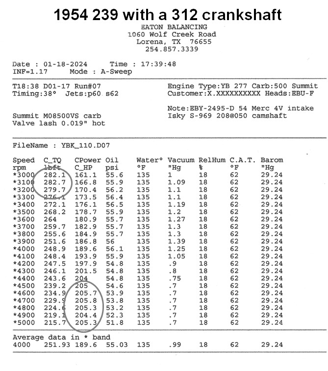
The 500 cfm Summit carb is running on the lean side at idle and with the idle adjustment screws being turned out 3 full turns, there’s still not enough idle fuel. The idle bleeds within the fuel discharge nozzles are switched out from the supplied 0.046” bleeds to 0.043” bleeds and that restores the idle fuel adjustment. Subsequent dyno runs on the engine has the horsepower peaking at 205 at 4700 rpm and the torque peaking at 282 @ 3400 rpm. Not too shabby for an engine that originally left the factory rated at 130HP and 214 lb/ft torque. This engine is now ready for installation back into its 1954 Ford pickup. The dyno sheet can be found at the end of this article.
So, there you have it. A 239 now becomes 277 cubic inches and is upgraded with some of the newer parts that are more readily available. Whereas the compression ratio was 6.91:1 upon arriving for rebuilding, it’s now at 7.71:1 with the 312 crankshaft and composite head gaskets. With over a fifty percent increase in the available power than when originally produced, this will be one very good running 1954 Ford pickup. Until next time, happy Y motoring. Ted Eaton.
Note: Originally written to be published in The Y-Block Magazine, Issue #172, Sep-Oct 2022. Was rescheduled to be in issue YBM #174 but issue #173 was the last one to be mailed out before the YBM ceased all publication. Ted Eaton.