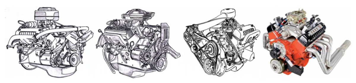
This is a continuation of a series of articles that goes into the different areas of the engine that can be worked on to increase the power and efficiency of the Ford Y. Keep in mind that many of these also apply to almost all other makes of engines and not just the Ford Y. These topics are in no particular order in regards to their benefits. Some are more beneficial when added or combined with others.
BLUEPRINTING
Clearances within an engine are just another key to an engine that performs to expectations. Not only are bottom end bearing and piston to wall clearances important, so too are any other pieces within the engine where movement takes place. The camshaft needs to turn freely; otherwise, it’s an additional drag on the engine. Using a neoprene rear main oil seal instead of the rope version frees up some additional horsepower. Add to this valve stem and lifter to bore clearances. Too tight on the clearances simply ends up being too much unwanted drag (friction). Likewise, being on the loose side is being counterproductive and in the case of the pistons, excessive piston to wall clearance can promote a loss of ring seal due to excessive piston rock. As the piston skirts become shorter, this becomes even more critical.
Added to this section would be certain assembly procedures. Using a feeler gauge between the rods that takes up all the free play as the rod bolts or nuts are being torqued helps to keep the bearings fully seated within the rod journals. When filing the ring end gaps, always do so with the file working inwards to prevent burrs from forming on the outer edge of the ring thus scoring or prematurely wearing the cylinder walls. While a ring gapping tool is preferable, gapping the rings in a vise with soft jaws is always an option. Using a belt sander or small file on the oil ring end gaps can at times remove a burr on those ring ends that is not normally found if not looking for them. Those oil rings with the less than perfect ends will scratch the cylinder walls if not taken care of before installing them on the pistons. Always deburr the ring end gaps regardless if they have been re-gapped or not. Assume nothing when it comes to the quality of the parts being used. Install the rings on the pistons using a piston ring installing tool. Installing the rings without a specific tool can put a twist into the rings if simply installing them by hand on the pistons.
BALANCING
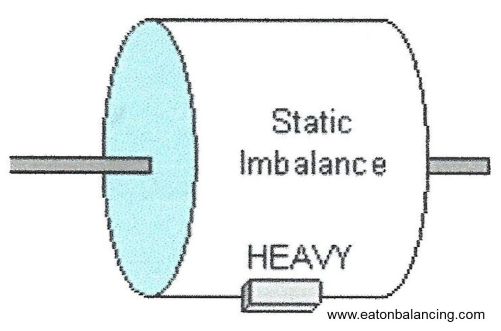
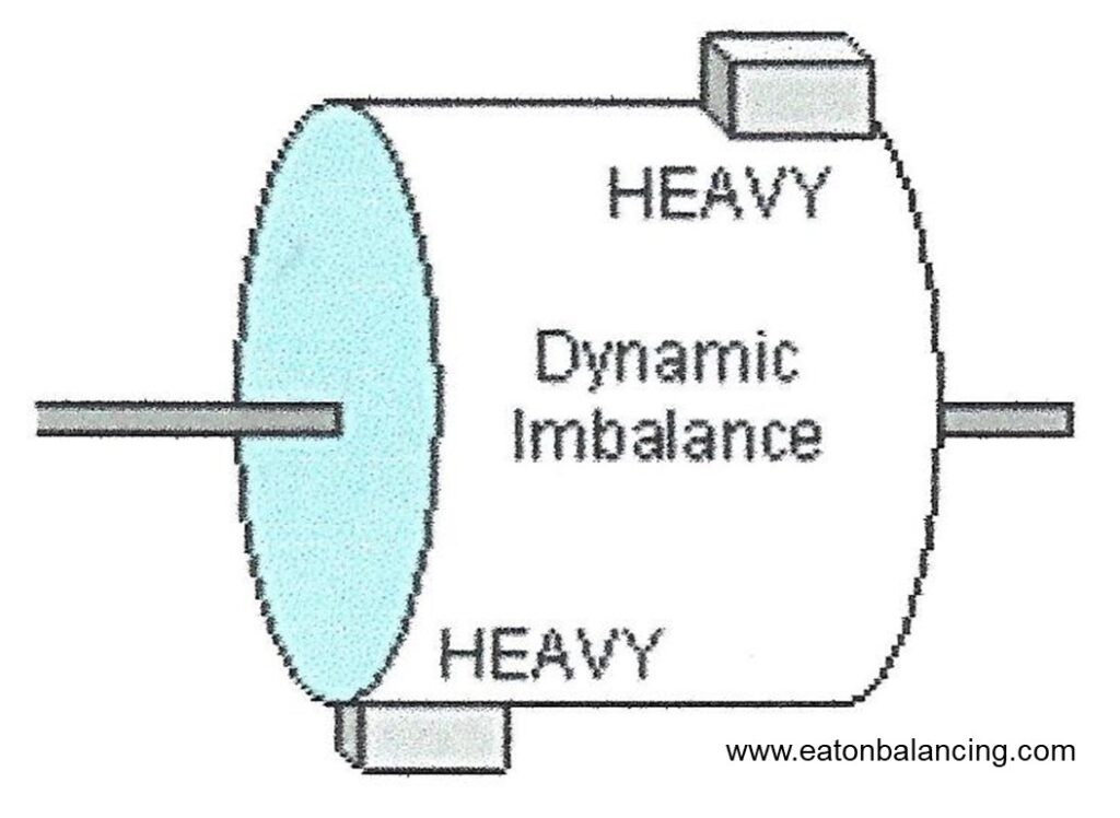
Balancing the rotating assembly of a freshly built engine is analogous to balancing new tires when you install them on the wheels. You would not think twice about not balancing those new tires and likewise, any time an engine has been rebuilt, the existing balance attributes should be examined. Whenever any of the rotating assembly parts are changed out within an engine, it’s always a good idea to rebalance the rotating assembly. There are two types of balance to consider: static and dynamic. Static is a single plane of unbalance as you would experience in a flywheel. Whenever dealing with a longer rotating part such as a crankshaft, then dynamic balance comes into play as you are dealing with balance aspects at each end of the crankshaft.
Due to the 90° nature of a V8, the weights of the pistons, connecting rods, and the related parts are directly related to balance of the crankshaft. If those weights change, then the crankshaft does need to be rebalanced to match those new piston and connecting rod weights.
Any amount of imbalance within an engine is transmitted to the confines of the block which in turn reduces the power output at the flywheel. Said differently, the more finely balanced an engine is, the higher the potential power at the flywheel due to a reduction in the destructive forces that results from imbalance. Balancing in general not only helps with the power production at the flywheel but also extends engine life and durability.
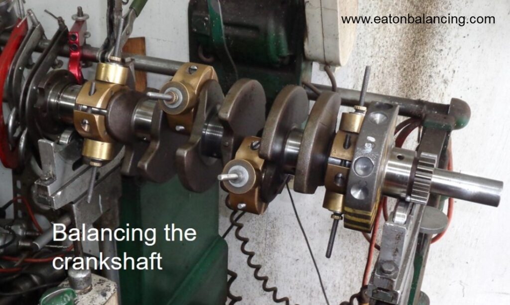
On a V8 engine, the crankshaft must be balanced to match the reciprocating and rotating masses involved. These masses would include the weights of the rods, pistons, rings, and bearings. Other factors affecting the overall balance would be those parts that simply rotate with the crankshaft which would include the harmonic damper, lower timing gear, and flywheel. If dealing with a standard shift transmission, then the clutch and pressure plate also become important players in the overall balance of an engine.
Any engine is capable of a given amount of power production based on its sum of parts and specifications. The amount of imbalance present will dictate exactly how much of that power becomes lost as unwanted vibration within the block with the remainder then being transmitted to the flywheel. When that power is distributed to the inside of the engine by lieu of ‘imbalance’, it results in accelerated wear in the bearings and crankshaft journals. If severe enough, then the various fasteners within and around the engine simply loosen over time and speeds up the demise of the engine. The degree to which the imbalance exists dictates the rate at which internal damage within the engine is happening. By having an engine professionally balanced, the amount of imbalance present is minimized thus allowing that engine to be smoother in overall operation, be more efficient, having a longer life span, and also have the potential for all the produced power being available at the flywheel.
Horsepower numbers as the result of balancing? That mostly depends upon the amount of imbalance present. While I haven’t tested imbalance scenarios on the dyno and have no plans to do so, I did have some real world experience with a friends drag race engine that was not initially balanced. This engine was having issues in revving to its full potential and after changing a multitude of parts on that engine failed to increase its performance, it was taken apart and balanced. The original state of balance was very much a worst-case scenario but professionally balancing the rotating assembly in this instance helped the car to pick up over a half a second in E.T. with no other changes. Whereas the engine was stalemated at 6800 rpm before balancing, it was easily capable of 7400 rpm after balancing. Considering the weight of the vehicle that this engine was in, that was an easy 75-80 HP increase in power output just from balancing the rotating assembly.
GAS PORTS IN THE PISTONS
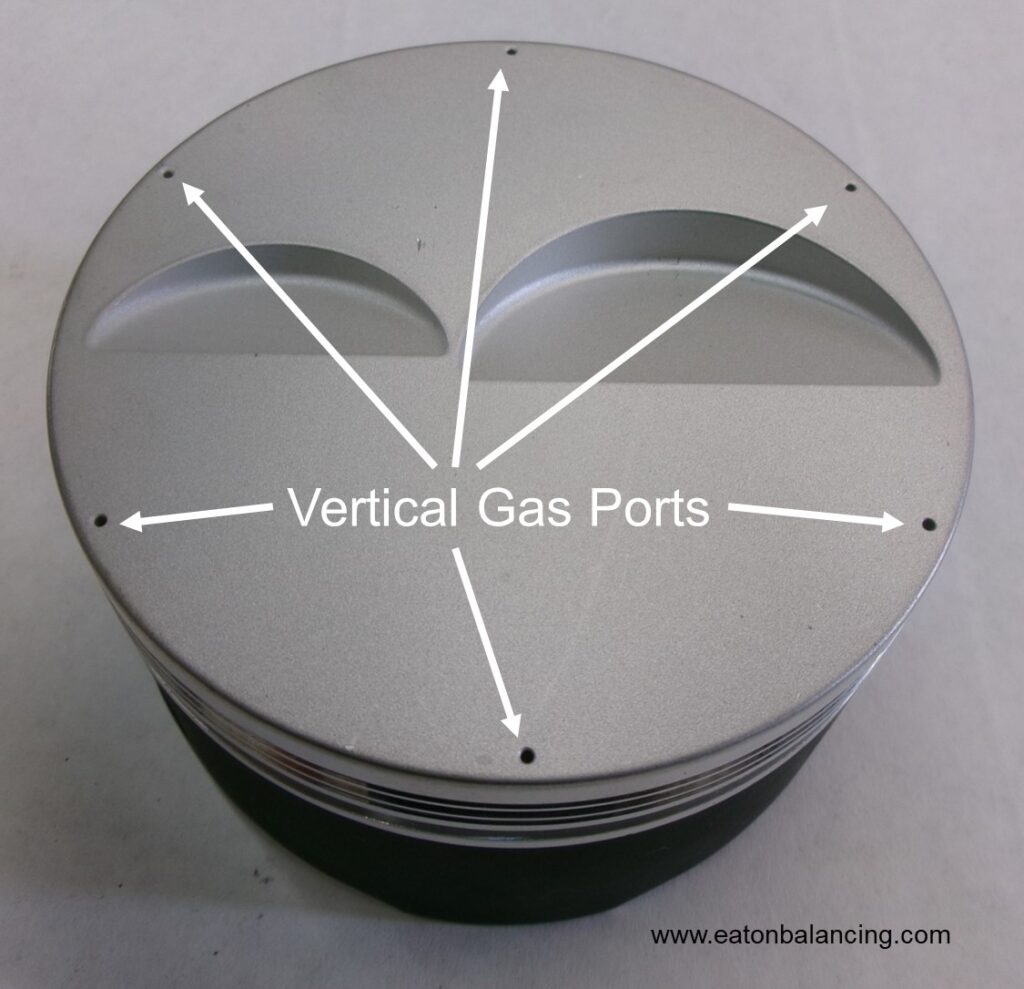
There are two styles of gas ports for the pistons; vertical and lateral. The style most people are familiar with are the vertical gas ports and these can be seen on the piston tops at the outer edges. Six to twelve ports are normal. These ports allow the compression pressure to go into the top ring land behind the top ring which in turn pushes the top ring outwards with increased pressure into the cylinder wall when the piston is under compression. The other style uses lateral gas ports and these are located in the sides of the piston located at the upper edge of the top ring groove.
For a racing application where the engines are serviced regularly and the pistons can be cleaned, the vertical gas ports are typically the design of choice. These particular ports are in a position to provide equal pressure to the inner circumference of the top ring. The disadvantage to this style of port is that the ports are prone to becoming plugged with carbon or deposits of burnt oil over time.
Where the engine is not being planned on being torn down so often, then the lateral gas ports are used; these do not have that same tendency to plug or stop up. With piston rock being a player, those lateral gas ports may not be allowing a consistent pressure increase around the inside of the ring and as such, are not as effective as the vertical gas ports. The Ford Y-Block engines entered by Eaton Balancing in the Engine Masters Challenges utilized lateral gas ports as some those engines were being repurposed after those competitions to be street engines with no plans for those engines to be torn down and serviced anytime in the near future. For the 2019 EMC Ford Y entered by Ted Eaton and Joe Craine, the rules were specific against having vertical piston gas ports but the rules did not prohibit the use of lateral gas ports. Sometimes the rules simply dictate the particular design being used.
Where the rules ban the use of gas ported pistons, then gas ported rings are another option. These rings will have the grooves or gas ports machined in the topside radial face of the ring. Gas ported rings are showing to be even more effective at piston ring seal than either the vertical or lateral gas ports in the pistons themselves. These rings are sensitive to the amount of area behind the rings and it may be necessary to use special spacers behind those rings to take up some of that excessive back space. Spacers for those rings are available in a variety of thicknesses so that the backspace or volume behind the rings can be tailored accordingly.
VACUUM PUMPS.
Maintaining a vacuum or negative pressure on the crankcase has seen as much as a 25 HP increase in peak numbers on 1000+ HP engines. Vacuum can be generated by a vacuum specific pump or can be generated by other means such as a dry sump oil system or an exhaust scavenging system designed specifically for that purpose. As a general rule, the higher the vacuum, the higher the horsepower to be gained from this. Care must be taken though in that as the crankcase negative pressure is increased, the oil pressure is decreased. Also decreased is the oiling that is provided to the wrist pins which in some forms of racing can prove to be detrimental which causes galling to take place in the wrist pin area. For a dry sump system to provide a horsepower increase, it will need at bare minimum a four-stage pump and a five-stage pump would prove to be more desirable. A three-stage pump is just enough to remove the oil from the dry sump oil pan but has no additional capacity to create a negative pressure in the crankcase. This is where the additional stages will be of benefit.
CAMSHAFT TIMING SETS.
The type or design of the camshaft timing set being used will have an effect on the top end horsepower. Most cam timing sets can be defined as one of three types; chain, belt, or gear. With a chain or belt, there is a given amount of elasticity present which allows the camshaft to retard as the rpms are increased. When those rpms are reduced, so too is the elasticity and the cam timing returns to its original starting point. A belt will exhibit more of this elasticity than a chain but it is present with either. The advantage to having the elasticity is that it is retarding the camshaft in the higher rpm ranges where it’s desirable to do so. The gear set on the other hand will keep the cam timing constant regardless of the rpm. Gear sets are popular in those racing venues where the rpm of the engine is constantly being ramped up and down such as in circle track racing. Many of the oem manufacturers used the gear-to-gear sets on six-cylinder engines where the cam to crank centerline measurements were small enough to accommodate a gear set. When those cam to crankshaft centerline measurements are increased to the point that gear sizing was too great, then chains would be used. The aftermarket gear drive setups use either a single or dual idler gears to keep the gear sizes reasonable while also allowing the camshaft to also turn the same direction as the crankshaft. For the Ford Y, timing chains were used on the majority of the engines. For the reverse rotation marine engines, a gear drive set without idler gears is used so that the camshaft could still rotate the standard direction. This eliminated the need for a specific reverse rotation distributor.
OIL PUMPS.
Oil pumps can be considered another horsepower robbing accessory such as a water pump or alternator (generator for those of you that still run one). As the oil pressure increases, so too does the load on the oil pump increase which in turn simply takes away from the power being transmitted to the flywheel.
The majority of oem oil pumps are designed larger than necessary to compensate for engine wear and other variables that can occur during the life of an engine. Most oil pumps have a relief valve to limit the amount of oil pressure and not over-pressurize the engine. Those oil pump relief valves also compensate for the pressure increase that goes along with the higher viscosity when the oil is cool.
For a racing application, the oil pump displacement can be reduced in an effort to increase the engines power output. The oem oil pump can be machined so that the rotors are actually smaller (not as thick) so that the displacement or volume is reduced thus reducing the amount of wasted or unneeded oil volume going to the relief valve.
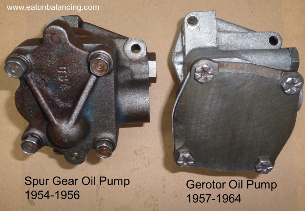
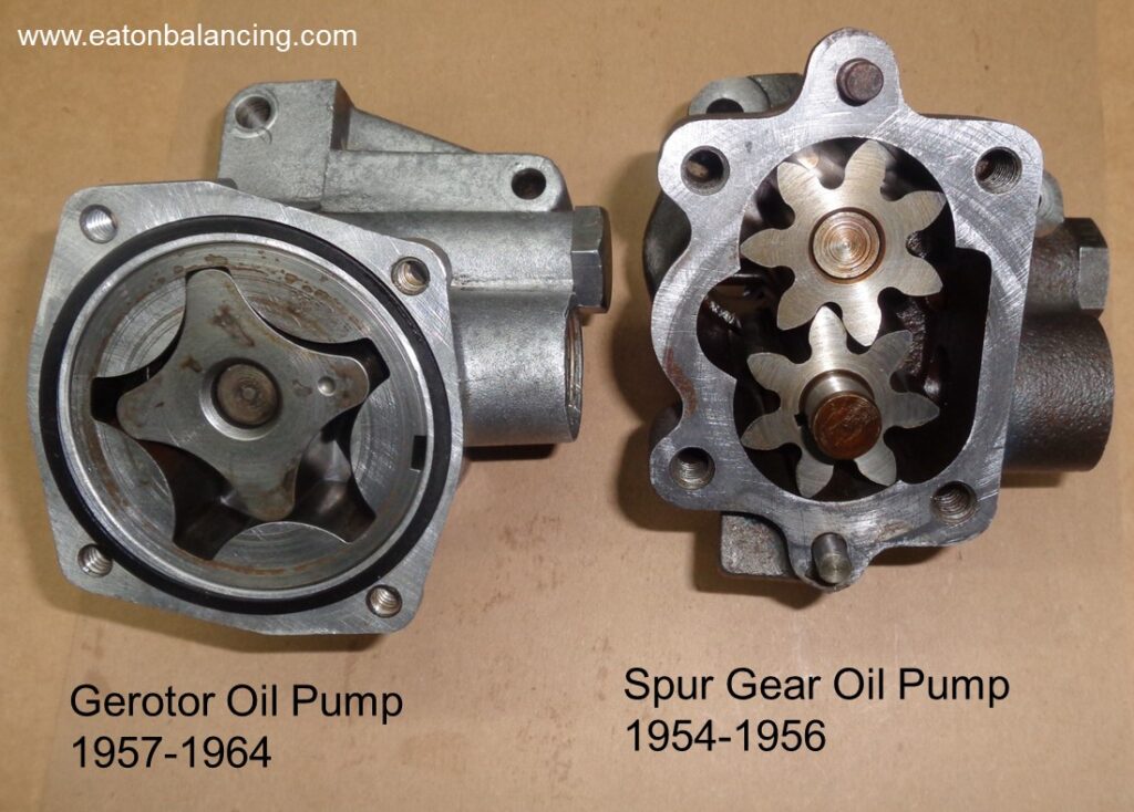
For the Ford Y, there were two different oil pumps available. From 1954 to late 1956, the spur gear oil pump was standard fare. The gerotor oil pumps made their debut with the mid-year 1956 Ford models equipped with the 312 engines. Starting with the 1957 models, all Y engines came standard with the gerotor pump. The new Ford engine families introduced for the 1958 models (FE, M-E-L) and later (SBF, 335 series, 385 series) all came with some form of gerotor oil pump. The gerotor pump is simply a more efficient design with the cavitation issues that were prevalent with the spur gear pumps being greatly diminished.
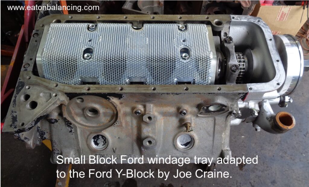
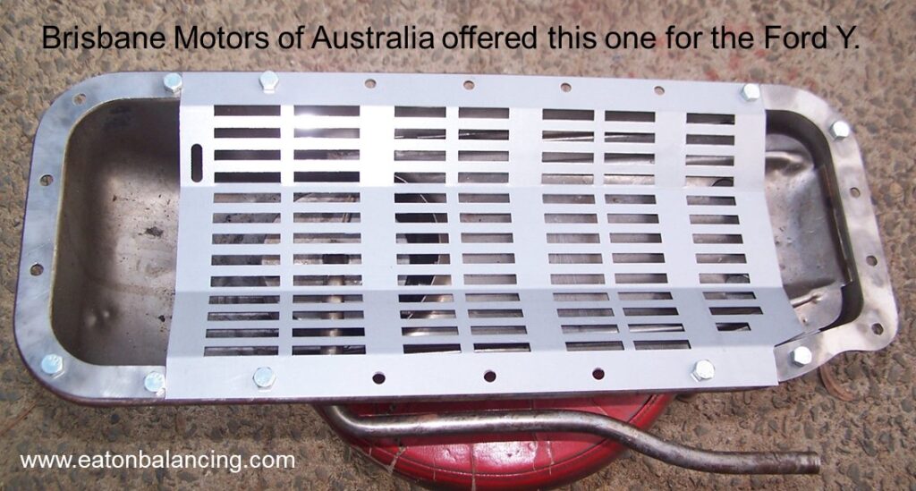
OIL PANS & WINDAGE TRAYS.
Anytime the oil can be prevented from being held in suspension around the rotating assembly, there will be an increase in power. The analogy to this is driving your vehicle through a deep water puddle as there is an obvious drag on the vehicle and more throttle must be applied to overcome that drag. The same holds true for oil that is hitting the crankshaft and connecting rods while they are moving.
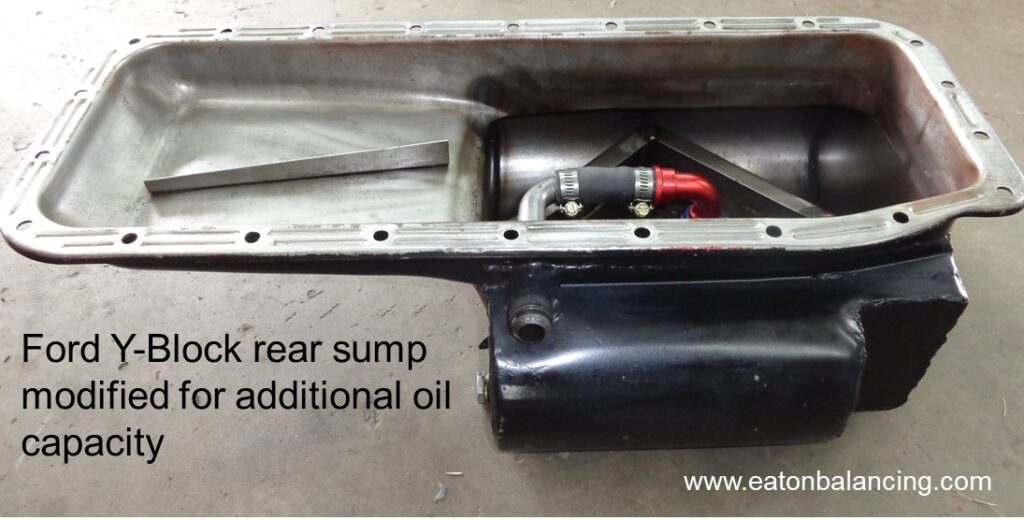
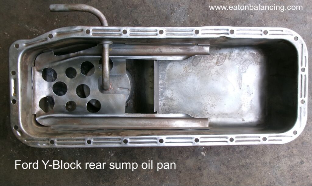
The obvious fix to this is to lower the oil level so that the crankshaft does not whip it up and back into the rotating assembly. In this case a deeper oil pan puts the oil level lower while still maintaining an amount of oil that keeps the engine from starving for oil. Another fix is a windage tray and/or an oil scraper that helps to keep the oil separated from the windage taking place around the crankshaft. There are a multitude of windage trays and oil scraper designs with some being more effective than others. I am partial to the grated and/or directional screens rather than the louvered style of windage trays.
Some of the newer designed engines do have separate paths for the oil that is returning to the sump so as not to go through the rotating crankshaft and connecting rods. This is being done to increase both the power levels and fuel efficiency. For the Ford Y, we are left with the factory option of the oil flowing to the front and rear of the engine to get back to the sump. At the rear, that returning oil does have to pass through the crankshaft and connecting rods to get back to the sump.
The combination of lowering the oil level and having a windage tray is worth at least six horsepower for the Ford Y.
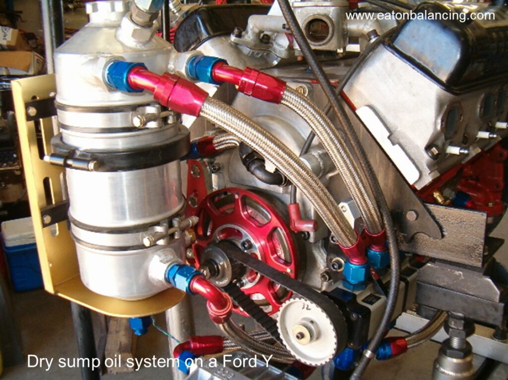
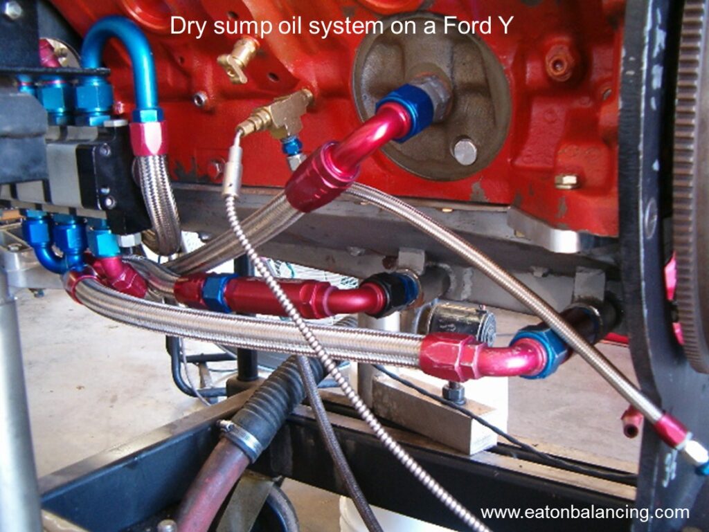
A dry sump oil system would be the ultimate fix as all the oil is constantly being removed from the oil pan when the engine is running. A windage tray and/or a crankshaft/connecting rod scraper in this instance is still desirable as removing any excess oil from the area of the rotating system is still needed. Oil pump sizing and pump speed is much more easily controlled using a dry sump oil pump rather than modifying an oem oil pump. For a dry sump oil pump, there is one stage dedicated to pumping oil to the bearings and the remaining stages would be connected to the oil pan for oil evacuation purposes. While a three-stage dry sump oil pump would prove to be adequate for removing all the oil from the pan while also providing oil to the bearings, additional stages would be of benefit as a vacuum can actually be generated in the crankcase which would also be beneficial to ring seal and additional power production. Another advantage for using a dry sump oil system is the pan can be quite shallow as there is no longer a need for a deeper sump in which to maintain an oil supply for the engine. A shallow pan solves clearance issues found in some applications.
CUBIC INCH … CUBIC INCH
That old adage that says “There’s no replacement for displacement” is still true today. And especially true where ‘cheap’ horsepower is to be found. While small cubic inch engines can be made to produce large horsepower numbers, these engines are far from inexpensive to build and operate in a rpm band that’s out of the realm for a normal street engine. Simply making an engine larger by increasing the bore and/or stroke is the least expensive route for those larger horsepower numbers. A 292 Ford Y bored 0.110” over and using a 312 crankshaft that is offset ground to a 3.600” stroke provides a quick cubic inch gain of 45 cubic inches. Considering that it’s quite easy now to attain that magic 1 HP per cubic inch number on a performance engine build, that 45 cubic inch increase is an easy 45 HP. With proper camming, head work, induction, friction coatings and other modifications, that 1 HP to cubic inch number can suddenly become 1.5 HP to the cubic inch. That original 45 HP increase from the cubic inch increase now becomes a 67½ HP increase. With continuing advances on reducing the friction within the engine, even higher HP/CI numbers are now possible which explains how those Ford Y horsepower numbers are now exceeding 600 HP when normally aspirated. Boosted applications break all the rules and is fodder for a completely different article.
EPILOG.
So, there you have it. Some tips for additional power. Some are obviously easy while others take some additional thought to get there. As always, just consider this as additional food for thought. Until next time, happy Y motoring. Ted Eaton
Note: The original plan was for this article to be published in The Y-Block Magazine issue #179. Due to problems arising from the publishing company reorganizing and then relocating, the YBM like so many other publications during the 2015-2022 time frame, simply went out of business.