This is a continuation of a series of articles that goes into the different areas of the engine that can be worked on to increase the power and efficiency of the Ford Y. Keep in mind that many of these also apply to almost all other makes of engines and not just the Ford Y. These topics are in no particular order in regards to their benefits. Some are more beneficial when added or combined with others.
HARMONIC DAMPERS
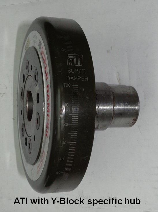
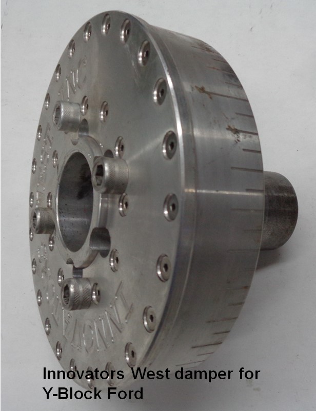
Harmonic damper testing also finds some hidden power for the Y. With extensive damper testing having been performed in the past on the Ford FE engines (390/427/428), it was already expected that some of the aftermarket dampers should also prove beneficial for the Ford Y engines. For this, there are dyno results available from two different Y engines. The first engine for this was a well prepped iron headed drag race 342” Y that was tested with three different dampers; a stock Y damper peaking at 497.3 HP, an ATI dual elastomer damper peaking at 500.1 HP, and the Innovators West (IW) friction style damper peaking at 501.5 HP. On this particular engine, the ATI damper was worth an additional 0.56% HP over the stock damper while the IW damper was worth 0.84% additional HP over the stock damper. The other engine used for damper testing was the 375” Engine Masters Challenge (EMC) entry which was tested with an ATI damper and the Innovators West damper. Testing on the EMC engine had the ATI damper peaking at 528.5 HP while the Innovators West damper peaked at 534.2 HP. In this case the IW damper was good for another 1.1% increase in horsepower over the ATI damper. In any kind of performance Y-Block build, an aftermarket harmonic damper is recommended. I’ll add that any horsepower gains being achieved with a damper is due to less destructive forces being at work within the engine itself and the damper is thus reducing those destructive or power robbing forces.
The aftermarket industry supplies several different styles of dampers for the various performance engines. The elastomer design as provided on many of the OEM engines is the most common where a rubberized material is used as an absorber to dampen unwanted harmonics occurring at the crankshaft snout. Other designs include liquid filled, friction, and ‘shock’ absorbing metal balls. All these designs have their merits if properly applied to their intended purpose.
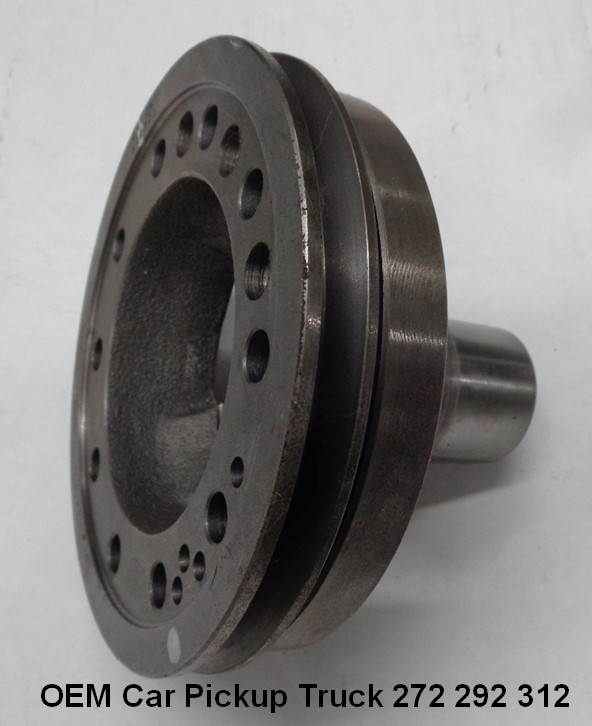
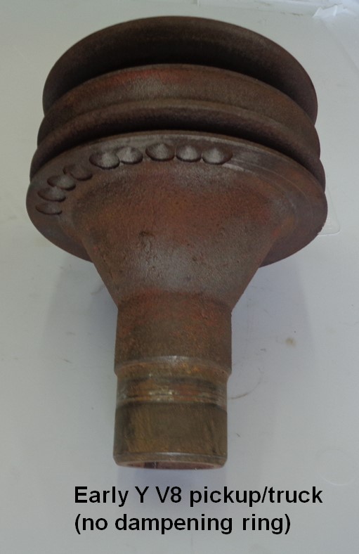
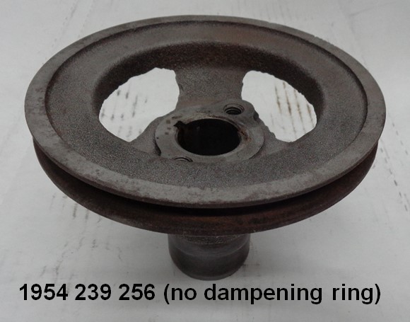
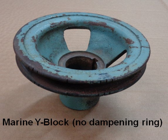
A general observation on the Ford Y-Block dampers is that the OEM car and pickup/truck dampers are only adequate for the stock engines. As the compression ratio and rpm band increases, so too does the need for a heavier and/or more robust harmonic damper. The factory 1955-1957 Thunderbird dampers are heavier than the standard car/pickup dampers and can be considered to be a step above the stock dampers from a performance standpoint. Even these will prove to be inadequate when the Y is modified for higher than stock performance levels. The 1954 Ford and Mercury engines as well as some of the pickup and truck applications did not incorporate a harmonic damper and instead simply had a solid hub with a belt pulley. Those solid hub dampers provide no crankshaft dampening and should not be considered ever for a performance application.
CYLINDER HEADS
Along with exhaust systems, cylinder heads and how they are modified are big players in the HP department. On the basically stock short-blocked +060 over 312 dyno mule, the stock ‘G’ heads peaked at 292 HP while a highly modified set of ‘113’ iron heads peaked at 333 HP. A pair of stock Mummert aluminum heads produced 354 HP while a set of ported aluminum heads made 377 HP. The compression ratio was 9.2:1 for both the stock G and the ported ‘113’ heads while the compression ratio for the aluminum heads was 9.8:1. All this testing was performed with the same Mummert aluminum intake manifold, 750cfm vacuum secondary Holley carburetor, and the same set of headers with mufflers. Ported iron heads in this instance are worth 14% over the stock heads, out of the box aluminum heads are worth 21% over stock, and ported aluminum heads are worth 29% over stock. If the baseline heads had been the smaller valved heads instead of the ‘G’ heads, power increases would have been even more pronounced.
While the stock heads incorporate an 18° valve angle, changing those valve angles to 16° pushes the power levels up another notch. Testing here at the shop with the Mummert aluminum heads finds an additional ~25-30 HP increase when changing those heads to the 16° valve angle. While attaining the 600HP number is attainable with the 18° heads, the 16° heads jumps those numbers well beyond 630HP.
COMPRESSION RATIO INCREASE
Best bang for the buck comes from increasing the compression ratio. Not only does the power output go up, but fuel efficiency also improves. While milling the heads is one option, machining the block decks so that the piston is sitting closer to the deck at TDC is yet another way to increase the compression ratio. Head gasket thickness is also another consideration while using a domed piston is yet another option. The fuel being used will be the limiting factor on how high the compression ratio can actually be so that must be also taken into account. As a general rule of thumb for a street driven Y engine, you can figure for a 2-5% increase in horsepower output for each full point that the compression ratio is increased. Specifically tailoring the ignition curve to the application as well as adding a free-flowing exhaust system helps to maximize the gains found by raising the compression ratio.
And this is a good time to bring up how the compression ratio calculation value is calculated. There is static compression ratio (SCR) and there is dynamic compression ratio (DCR). The SCR is the compression ratio most often discussed as that is simply the volume of the cylinder as measured with the piston at bottom dead center versus that volume which is found at top dead center. DCR on the other hand takes into account the connecting rod length and the intake valve closing event and essentially gives a value of what the engine sees once the intake valve has completely closed. Until the intake valve closes, actual compression within the cylinder as it comes up to TDC does not occur. Simplified, as the intake valve closing event occurs later, then the DCR decreases and likewise, an earlier intake closing event increases the DCR. While not as significant as the intake valve closing event, the connecting rod length is also a consideration. The rod angle being more extreme as result of being shorter will generate a higher DCR value while the connecting rod being longer will generate a lower DCR value. The DCR value comes in handy as it is more exact in determining what octane fuel the engine will be happy with.
ROD/STROKE RATIO
Dividing the connecting rod length by the crankshaft stroke gives you the rod/stroke ratio. Generally speaking, it is preferable to avoid those circumstances where the R/S ratio is less than 1.5:1. As the rod/stroke ratio number increases, the required number of degrees of ignition advance before top dead center reduces. This has to do with the amount of residence time that the piston is actually residing at TDC which increases as the connecting rod length become longer. On the flip side of this would be a rod stroke ratio that is lower by using a shorter rod. In this scenario the low-end torque characteristics of an engine are increased. This has to do with a quicker take away speed from TDC when using the shorter rod versus that of a longer connecting rod which has the intake flow into the cylinder being stronger earlier.
The camshaft is also a consideration when changing the connecting rod lengths as the residence time of the piston at TDC has a direct relationship with the lobe centerline or degrees of overlap that the camshaft has. The longer connecting rod equipped engines prefer camshafts with increased lobe centerline angles while short rod engines have a preference for camshafts with reduced intake and exhaust lobe centerlines.
The 2011 EMC Ford Y engine was assembled using a 6.750” long connecting rod. This was done knowing that the fuel being supplied to the event was 85 MON (Motor Octane Number) and in order to make the engine more fuel detonation resistant, the connecting rod was made as long as possible so that a more complete burn of the compressed fuel could take place. For that combination, the wrist pin compression height was exactly 1.000” which made for a very tight piston ring package. The wrist pin for that particular engine was the Ford 4.6/5.4L mod motor pin being 0.866” diameter versus the stock Y pin diameter of 0.912”. That smaller wrist pin diameter did give just a bit more wiggle room for the ring package but the ring package at the top of the piston was still very ‘tight’ even with the oil ring falling across the wrist pin hole. An oil ring support rail was used to add stability to the oil ring. That engine still runs good to this day in another application without any issues.
CAMSHAFTS
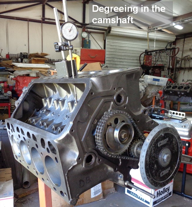
While the camshaft itself must be suited for the application for which it is going to be used, it’s important that it be degreed in when being installed in an engine. Manufacturing tolerances can have a camshaft far from its optimum installed position. Some of those manufacturing areas include the location for the camshaft keyway or dowel, the cam gear key slot or dowel hole, the crankshaft key location, and the lower timing gear key or slot location. When the various manufacturing tolerances stack up as either all positive or all negative, then the installed error can be substantial. This is all easily corrected when degreeing in the camshaft but if simply relying on aligning the timing marks or counting the pins on the chain to install a camshaft, then it’s going to be pot luck on the camshaft actually being installed at the cam grinders recommended position. If the camshaft is not degreed in, then it’s not known where it’s installed and is an area that may have to be revisited later if the engine fails to run correctly or as expected.
When degreeing in the camshaft, it is recommended to check at least one pair of camshaft lobes on both engine banks. On the Ford Y, cylinders #1 and #6 share the same TDC on the degree wheel so it’s a simple matter of just moving the dial indicator over to cylinder #6 after checking #1 and verifying that both banks are degreed the same. Within a sixteen-month span here at the shop, I came across three different Ford Y camshafts that were ground on the wrong lifter bank angles. This was only found by checking lobes on both banks of the engine. For the Ford Y-Block, the lifter bank angle is 86°. There are some cam grinders out there using 82° for the Ford Y lifter bank angle when grinding the camshafts and that will simply have one bank of the engine running four degrees different from the other bank. If trying to optimize the performance and efficiency of the engine, the camshaft opening and closing events do need to be the same for both banks.
For the Ford Y, the camshaft selection must take into account if the engine is iron or aluminum headed. If iron heads, valve lift can become a problem if exceeding 0.535” as the intake valve can contact the edge of the cylinder wall. While notching the cylinder walls can allow valve lifts approaching 0.600”, care must be taken when doing this as to avoid the cylinder wall area that the top piston ring resides. With the intake valves moved inboard 0100” and up 0.100” on the aluminum heads, the problem with the intake valves hitting the edge of the cylinder wall is not an issue. This frees up the intake valve lift limitation that was present with the iron heads. When going to that next level of valve lift, another problem crops up when the net valve lift goes over 0.600” for either the intake or exhaust valves. As the camshaft base circle gets smaller to obtain more lobe lift, the lifter also drops lower in the lifter bores when the lifter is in its relaxed state. A 1.510” camshaft base circle is the lower safe limit with the stock lifters as any smaller than this, the lifter can bind up in the lifter bore. Where the lifter drops too far within the bore, a chilled iron or cast-iron lifter will have a tendency to break at the stem to lifter face junction; always disastrous when that happens. The fix for this is the Trend lifters ordered with an additional 0.250” of stem height. With the additional lifter stem height, valve lifts in excess of 0.700” are now possible without the fear of a catastrophic cam and lifter failure. Why 0.700” or more lift? Those aluminum heads with just a little bit of porting love all the lift you can throw at them. More lift; more power.
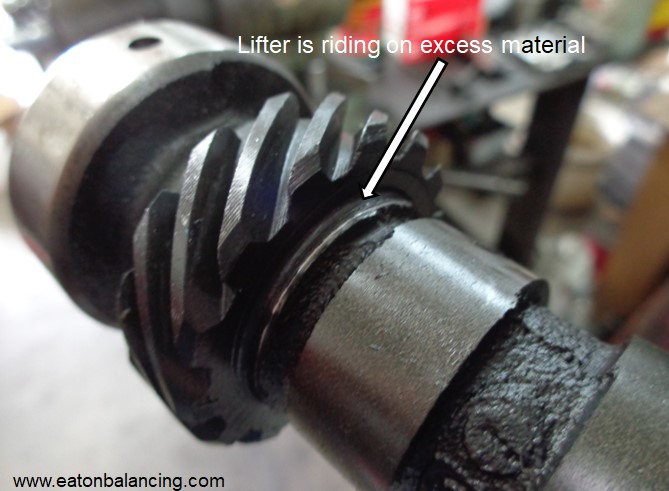
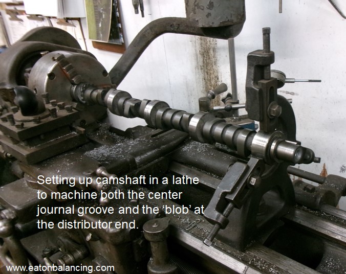
Another issue that crops up on the Y camshafts is a blob of material on some of the newer cam blanks just in front of the distributor gear. That area must be checked to ensure that the lifter on the last lobe on the camshaft clears that ‘blob’ of material when the lobe is at a zero lift position. Checking that area before installing the camshaft is a good time to catch that and if there is an interference issue, that ‘blob’ of material can be machined in a lathe so it clears the lifter.
But here are some general observations on camshaft selection. As the cylinder head flow increases, so does the need for an increase in the lobe centerline angle on which the camshaft lobes are ground. This is also true for cubic inch increases assuming the head flow matches the cubic inches. On the flip side of this, if wanting more rump in the camshaft, then decrease the ‘as ground’ lobe centerline value. This may require a reduction in the duration to restore or increase the intake manifold vacuum for low end drivability and/or vacuum operated accessories such as power brakes.
Race engines tend to prefer camshafts that are symmetrical or the lobes ground where the intake and exhaust lobes are the same. Special nuances such as where longer exhaust systems are being used or the cylinder head flow is restrictive on either the intake or exhaust valve may require non-symmetrical grinds; this is where the intake and exhaust lobes will be ground differently. Where the compression ratio is low, then the lobe centerline prefers to be less than in those instances where the compression ratio is higher. Advancing the camshaft typically always helps low end torque and part of that is a function of the intake valve closing earlier which then allows for the cranking or low rpm cylinder pressure to be higher. Likewise, retarding the camshaft tends to help top end performance. The intended application will be the final word for what the duration, lobe centerline angle, and how the camshaft is ultimately installed in the engine. When in doubt on this, always consult with your cam grinder for their recommendations.
MORE TO COME
This concludes part II of a multi-part series on the different items that can be performed on the Ford Y (and most other engines for that matter) in improving both the power and efficiency of those engines. The next article in this series will start off with intake manifolds and then in no particular order, will go into other areas of the engine where changes can be made.
Until next time, happy Y motoring. Ted Eaton.
Note: The original plan was for this article to be published in The Y-Block Magazine issue #176. Due to problems arising from the publishing company reorganizing and then relocating, the YBM like so many other publications during the 2015-2022 time frame, simply went out of business.