By using just the right combination of parts, exceeding that magic 1HP to cubic inch ratio is indeed possible while still doing it with a pair of unported iron Ford Y-Block heads. The key here is in using a modern piston ring design and maximizing the compression ratio while still being able to have an engine that will run on available pump gasoline. Not to be left out are the intake, carburetor, camshaft, and cylinder head choices which are also just as important.
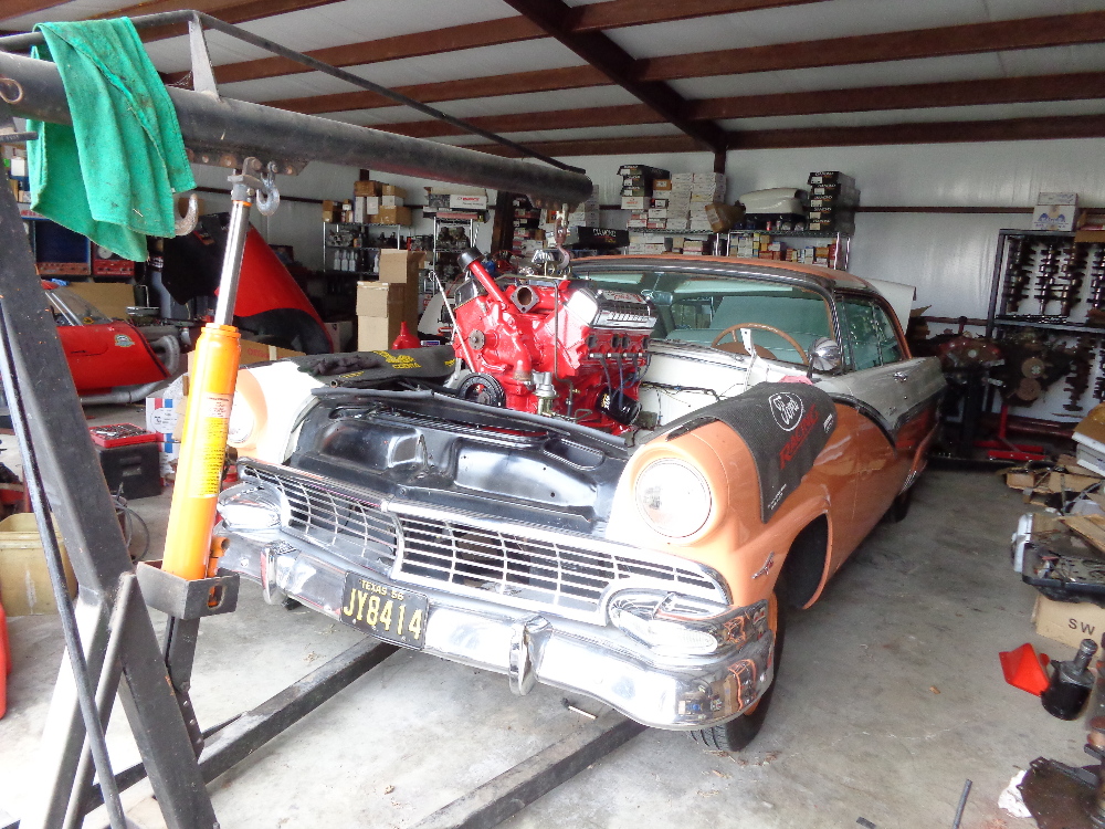
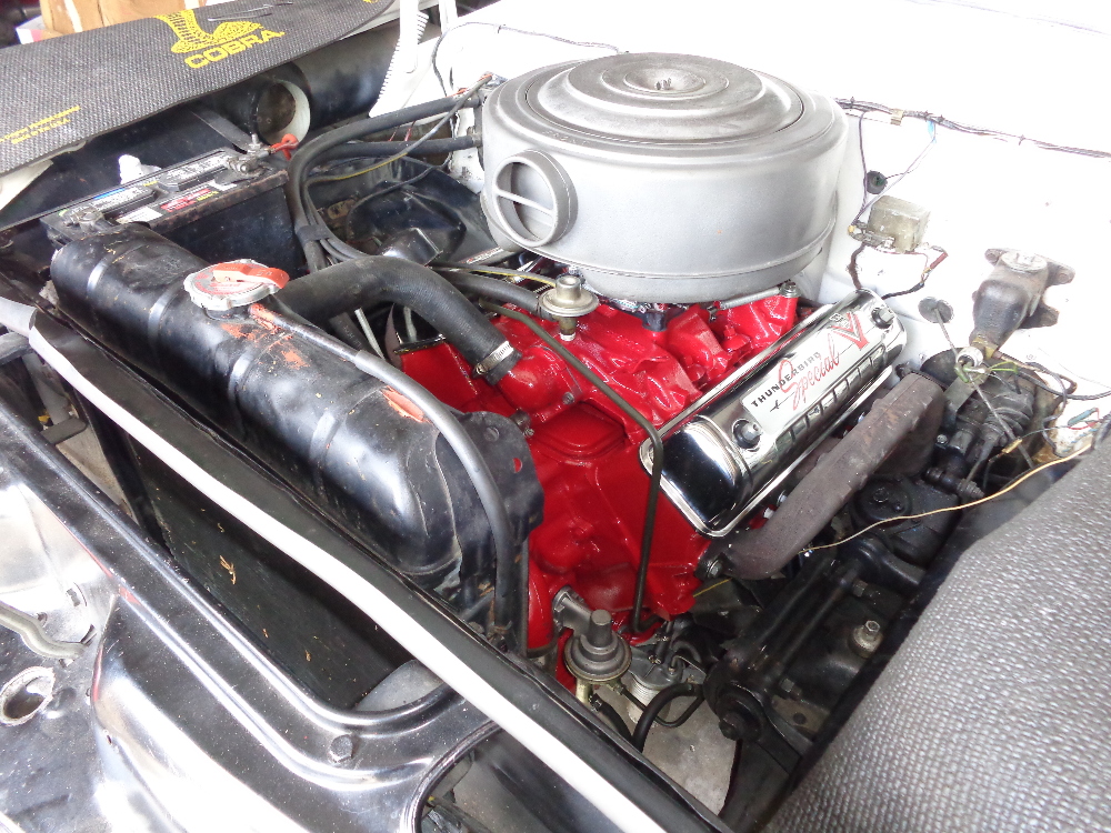
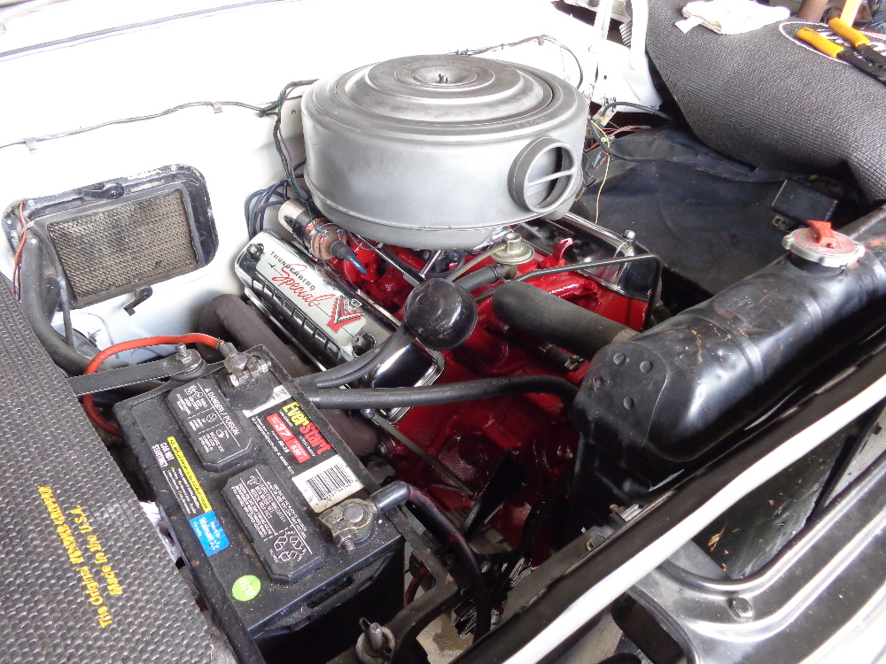
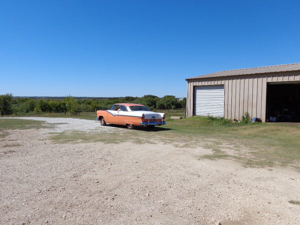
For this build, the engine is going back into Karol Miller’s 1956 Ford Victoria with a T86 3 speed/overdrive. The rear gearing is currently 3.22:1 which is going to drop the rpms significantly when the car is in overdrive mode. This makes low rpm torque production even more important. Because this car is not going to be sitting dormant in a garage very much, fuel efficiency needs to be reasonable so the camshaft choice becomes critical in making power while still being efficient.
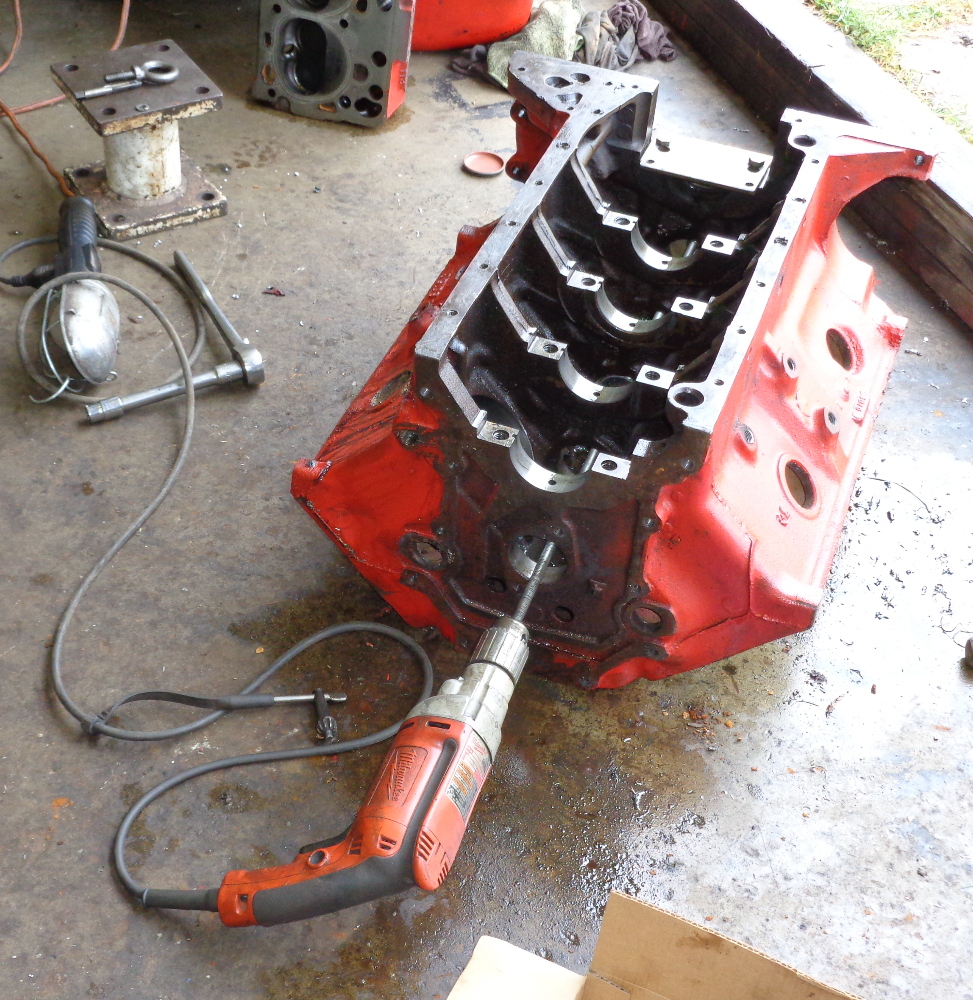
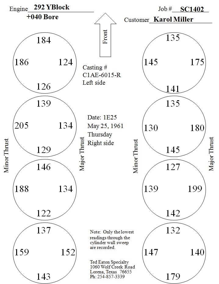
Because the block that comes out of the car is already 0.110” over and is badly worn, another block is picked out. The C1AE block selected for this build has a May 25, 1961 casting date and while it had already been previously bored 0.040” over, it is heavily worn again at this point. The block is sonic tested and deemed a good candidate for an additional over-bore. Prior to doing any machine work to the cylinders, the two center ‘steam’ or vent holes in the decks were plugged. The cylinders clean up at 0.070” over the stock bore size which will have the cubic inches coming in at 303 using a stock 3.3” stroke crankshaft. The center cam hole in the block is modified with an interconnecting groove between the three holes there to insure adequate oiling to the top end of the engine. Adding that groove has become a standard activity on Y engine builds at this shop as it alleviates any concerns about the new cam bearings pushing babbit into the camshaft journal groove and subsequently shutting off the oil supply to the top. While there are a couple of other fixes for this, the machined groove is my own preferred option for increasing the oil supply to the top end of the engine.
Click on picture for larger image
As an upgrade to the performance and efficiency, it’s decided to go with a modern ring design. For this engine, 1.2mm metric rings will be used for both the top and 2nd grooves with a 3.0mm oil ring finishing up the ring package. The original 2nd ring thickness was 3/32” which equates back to a 2.4mm ring. The new ring package cuts this in half which in theory cuts cylinder wall drag in half. But the metric rings also have less radial thickness which further reduces the ring drag.
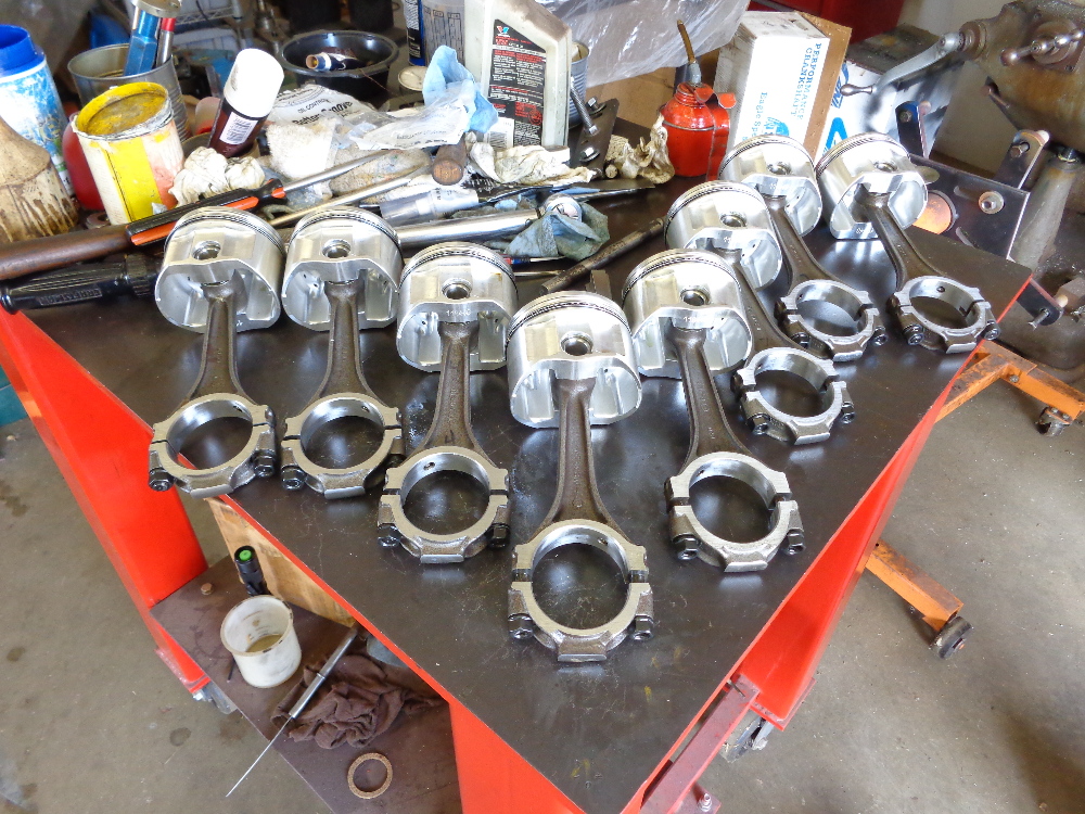
The connecting rod choice could have gone with either the longer 292 rod or the shorter 312 rod. While the shorter rod tends to allow for more torque production by lieu of an earlier piston movement from TDC, the drawback is an increase in the cylinder wall wear. The longer rod on the other hand does allow for an increased dwell time at TDC which in turn will help to deter any detonation issues that could be encountered as a result of maximizing the compression ratio for both power production and fuel efficiency. Piston skirt friction will also see a reduction with the longer rod versus that with a shorter rod. Because fuel efficiency is being considered, a set of ‘longer’ C2AE rods will be used for this build and are prepped and resized with new ARP rod bolts being installed.
Diamond Pistons supplies a set of custom flat top pistons for this build which permits the use of the aforementioned 1.2mm rings. These pistons have a wrist pin height of 1.792” and use a stock dimension 0.912” diameter wrist pin. The piston to wall clearance for this combination is maintained at 0.004”. The final deck height for the block after all the machine work is complete is 9.750”.
Click on picture for larger image
The remainder of the short block build presents no problems. The crankshaft comes from a 272 and is still a flawless standard on both the main and rod journals. In fact the clearance on the rod journals is still on the snug side with the replacement standard size bearings which is where a set of the red/blue bearings that use to be available from Ford would have come in handy. While the rod bearing clearance is on the snug side, it’s not so tight that it will be a problem. Once the engine has been mocked up and the decks machined for a zero piston to deck clearance, the rotating assembly is precision balanced with the crankshaft being balanced to an 1890 gram bobweight value. A small amount of overbalance is also included in the bobweight calculation which tends to extend the overall engine life. The oil pump is a stock gerotor oil pump that has simply been disassembled, examined for problems, and reassembled.

Click on picture for larger image
The cylinder heads came off the original worn engine and had been worked on not that many miles ago. They are a set of 113 castings which already had hard seats previously installed. While the exhaust valves were okay to reuse, the intakes were replaced with a new set of 1.92” stock sized valves. In measuring the pads at the exhaust side of the heads, it was found that both heads had had ~0.080” removed from them in the past. While that sounds extreme, the heads are factory posted and looked to have been running okay like this. In cc’ing the heads after reinstalling the valves and hardware, the combustion chambers are averaging 62.3cc’s. Calculating the static compression ratio for this combination has it at 9.57:1.
The camshaft selected for this build is an Isky grind with the following specs:
Duration at 0.020”: 264°I, 272°E
Duration at 0.050”: 228°I, 238°E
Lobe lift: 0.298”I, 0.320”E
Valve lift: 0.459”I, 0.493”E before valve lash
Ground on 110° lobe centers
Installed at 105½° intake lobe centerline
(4½° advanced)
With a stock link style timing chain set in place, the camshaft was sitting more than nine degrees advanced which was unacceptable in this case. Instead, a Rollmaster roller timing set with the multi-indexed crank gear is used which makes camshaft phasing much simpler. The dynamic compression ratio calculations when taking into account the 4½° of cam advance and using the 6.309” long connecting rods is 7.99:1. This engine will like premium fuel which is typically recommended anyhow simply due to the reduced amounts of ethanol in premium fuel versus that in the lower grades. The valve train is topped off with a set of rebuilt 1956 1.54:1 rocker arms and a set of 7.964” effective length tubular pushrods.
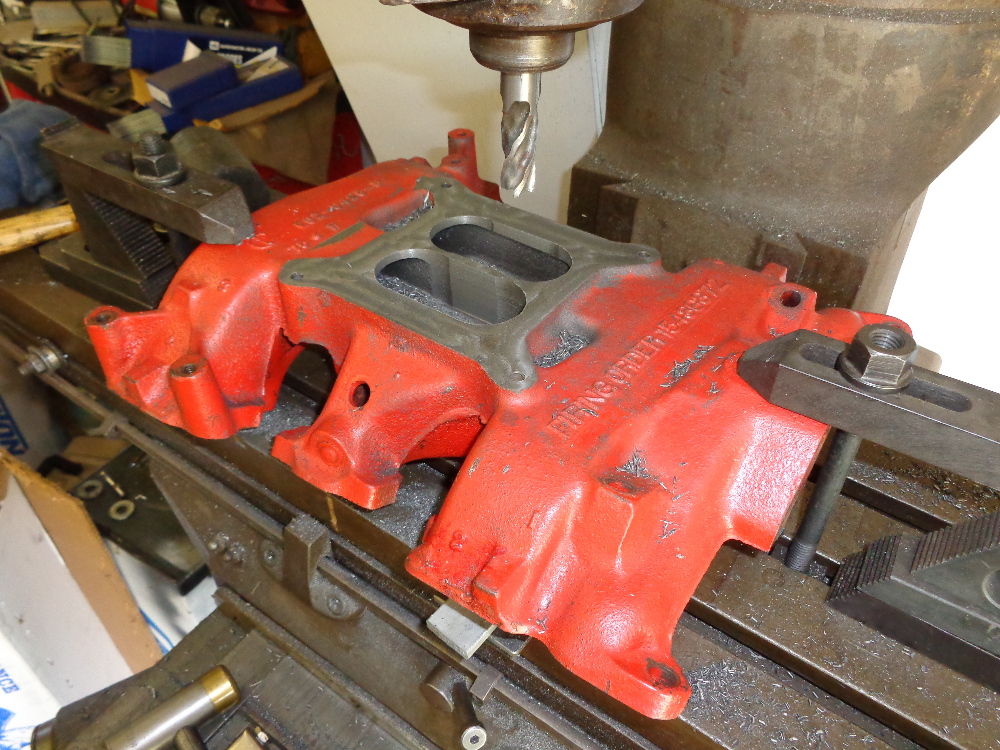
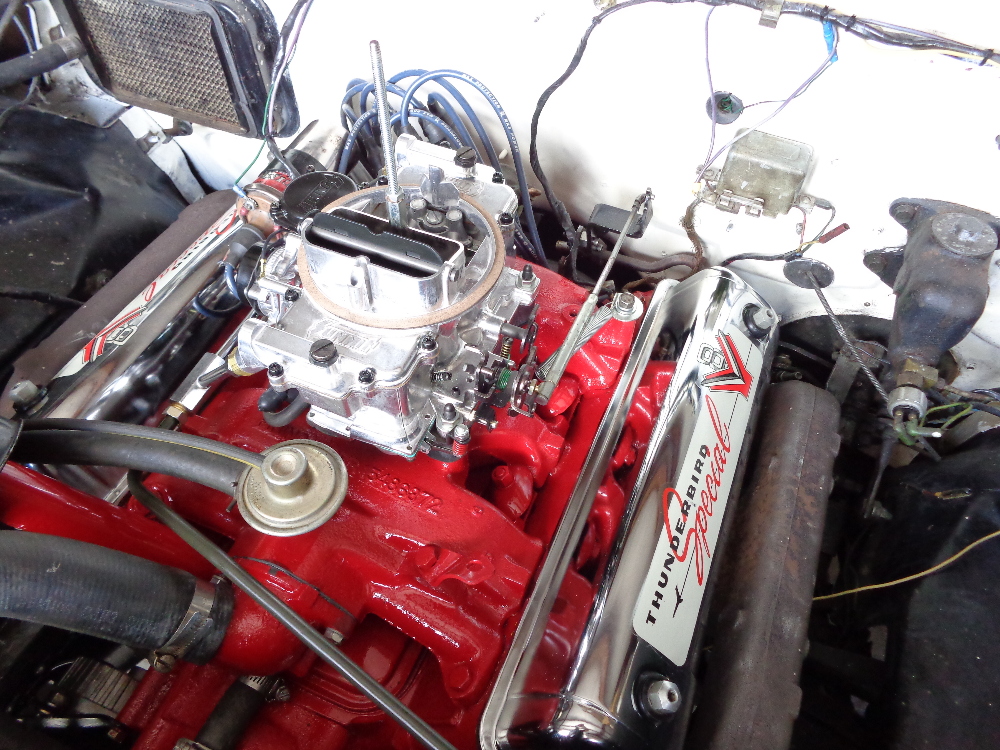
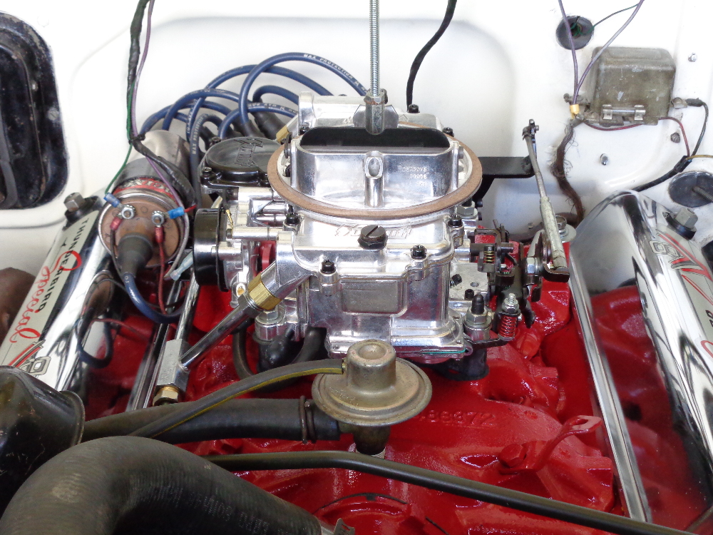
The intake manifold is the old reliable ECZ-B intake found on the 1957 and up four barrel equipped Y’s. The four holes at the carb base were opened up so it was dual slots and the transitions going to the lower ports ground on to open up the flow some. While it took about forty minutes to machine the dual slots at the carb base, the porting on the inside of the manifold took less than five.

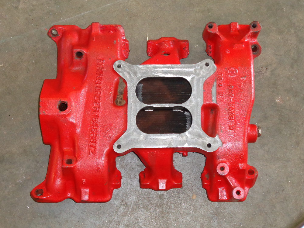
Click on pictures for larger images
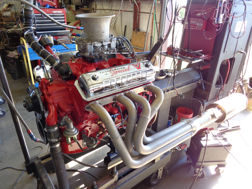
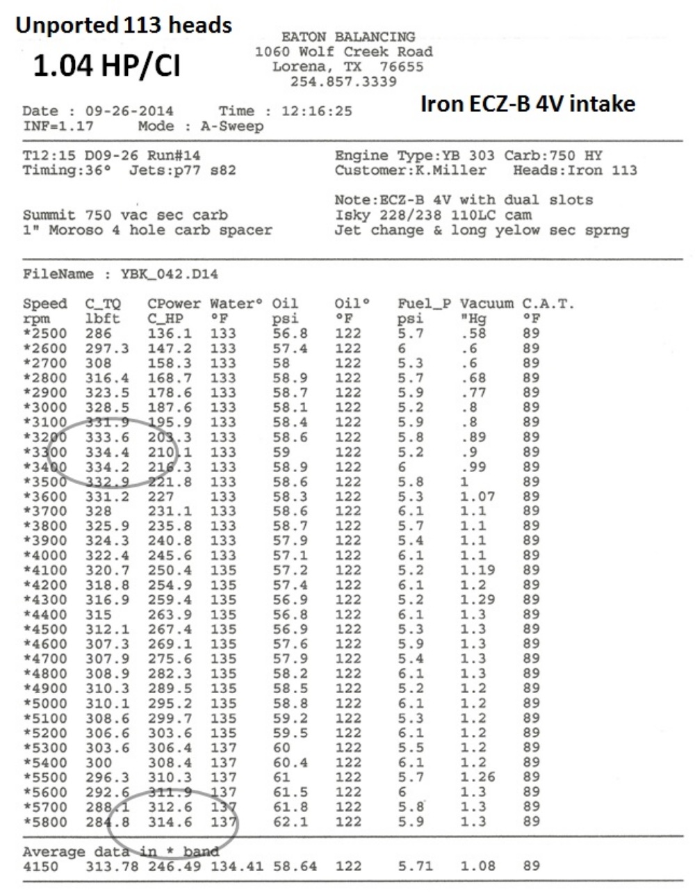
With engine assembly now complete, the engine is prepared for running in on the dyno. Six quarts of Valvoline 10W-40 conventional oil fills the pan and a Wix 51515 oil filter completes the package. The engine is initially started up with the shop’s 750 cfm HP Holley in place as this is a proven performer. The carburetor sits atop a 1″ tall four hole phenolic carb spacer. Once the engine is started up and run in, the valve train is checked for any problems and there are none. After the engine has been allowed to thoroughly cool down to put a completed heat cycle into the new valve springs, some dyno pulls are made. The engine immediately makes 308 HP and with some timing adjustments, jumps to 316 HP with the HP Holley on it. Karol’s 1956 Lincoln Teapot carb is put on the engine with an appropriate adapter and after jetting adjustments, it’s making 294 HP. But that carb simply has a hard time idling with this camshaft and has other issues with it that will require some serious work. There’s an older model 4010 750 cfm Holley sitting here that is tried and that carb runs nicely and clicks off a 315 HP number without any jet changes. Based on Harry Hutten’s recent performance with the Summit 750 carb that he is using on his ’60 Merc, a similar Summit 750 carb is ordered for this combination. Two days later the carb arrives at which point it’s immediately installed on the engine which is still sitting on the dyno. The engine idles well and with a three number increase in jetting on the secondary side only, another 315 HP number pops up.
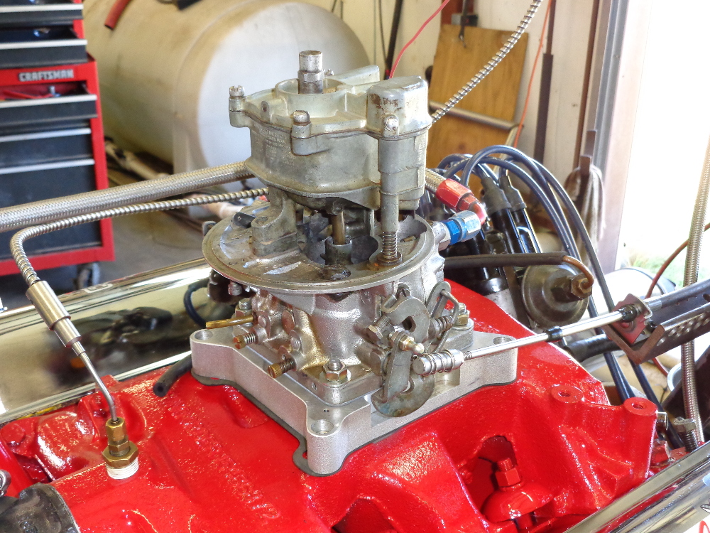
Click on pictures for larger images
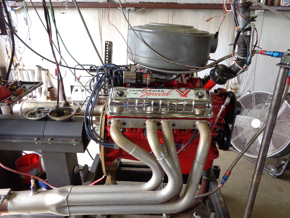
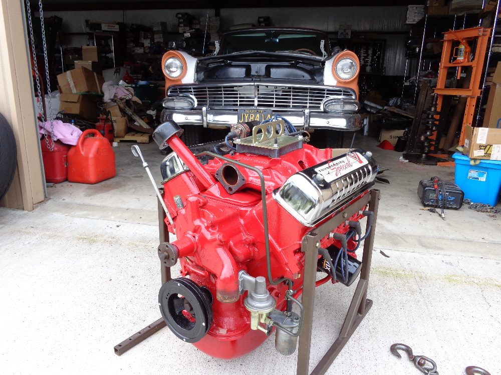
At this point, the engine is deemed good to go and reinstalled back in the 1956 Ford Victoria chassis. The engine was dynoed on a Friday and is back in the car and running on the following Saturday. That’s a quick turnaround. Since then the car has been driven around and drives without issue even with the 3.22 rear gears. Starts up good when cold and actually runs on the cool side with no heating issues at all. The exhaust lets you know that this is not a stock Y though. There’s a nice rumble from the pipes and that hard rush of air hitting the pants legs lets you know that the compression is there also. While it hasn’t been driven around enough yet to get an accurate mpg number, the fuel mileage doesn’t appear to be bad though based on the 120 miles it was driven around locally before going back home.
Click on pictures for larger images
The sonic test sheet and dyno sheet are also included at the end of this article. Until next time, happy Y motoring. Ted Eaton.
Click on pictures for larger images
This article was previously published in The Y-Block Magazine, Jan-Feb 2015, Issue #126.