Like any engine that’s in its planning stages, particular care must be paid to that engines intended use in order to select the correct parts and maintain those clearances that would be considered optimal for that combination. In the case of the blown engine for Randy Gummelt’s rear engine dragster, I’ve already covered some of the parts selection as well as the main support girdle construction in previous articles. At this point, I’ll cover in more detail some of the specific clearances and specialized machine work that was required to make Randy’s engine a reality.
The C2AE-C block was rough bored to 3.797” and the main journals align honed so that the engine could be initially dry assembled. The rotating assembly was installed within the block without piston rings which allowed for some preliminary measurements to be made and in particular, connecting rod to camshaft clearance and determine how much would be required to remove from the deck surfaces to obtain the desired piston to deck clearance. Used bearings were installed on the crankshaft at this stage to prevent any potential damage to the new bearings. There are no deep pockets in this operation so saving a buck where possible is always a consideration. Upon removing the rotating assembly from the block, the head bolt holes in the block are drilled and retapped to ½” X 13 and the cylinder bores are notched at the intake valve locations to both aid flow and increase valve to cylinder wall clearance in this area. Care is taken to insure that the cylinder wall reliefs do not protrude into the top ring area when the piston is at top dead center. The block is now ready to go back to the machine shop for final cylinder wall honing and block decking. All the hardcore machine work on the block including align honing the mains was performed by Lonnie Putnam in Gatesville, Texas.
The Moldex steel crankshaft is fully counterweighted which alleviates some of the balancing issues that comes from using heavier connecting rods and piston combinations as well as potentially reducing some of the crankshaft flex that can be associated with high horsepower and/or high rpm applications. The crankshaft was balanced using a 2015 gram bobweight value which includes a calculated amount of ‘over balance’ to compensate for the blower application on this engine. As a point of reference, a typical bobweight value for a normally aspirated stock Y-Block rebuild will fall in the 1960-2050 gram range.

The Eagle H-Beam connecting rods are an off the shelf item that are 6.125” long and specific for a 2.000” journal and work with the 0.927″ pins being used in the pistons. These were surprisingly quite economical and should be considered viable options in even a moderate performance build up as opposed to just reworking stock rods. The rods did however require some modification at the top of the rod bolt area in order to clear the camshaft adequately and this is a result of just pushing the stroke out to 3.800”. Although only a pair of the connecting rods would have required specific modification for adequate camshaft lobe clearance under a normal camshaft timing event scenario, all eight rods were clearanced in the event of a catastrophic failure in the cam drive. Minimum connecting rod clearance to the camshaft was targeted for 0.050”.
![]()
The Wiseco pistons are machined for 1/16” rings in both the first and second grooves while the oil groove is the common 3/16” size. The top ring is also spaced 0.330” down from the piston top instead of the more typical 0.250” spacing. The rings are provided by Total Seal and have a gapless style top ring which was deemed a necessity considering the supercharged nature of the engine. The main thought process here is to minimize the amount of alcohol that’s ‘blown’ past the pistons and into the crankcase. Of lesser consequence but still worth considering is that gapless rings also minimize the amount of leakage that’s created by cylinder wall wear which equates to 0.00314” of additional ring gap for each 0.001” of cylinder wall wear in a standard production ring set. Unlikely that this engine will ever see enough service to make cylinder wall wear and the effect on ring end gap significant, but is a factor regardless.
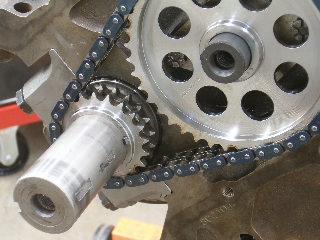
The Iskenderian camshaft is a custom grind and is designed specifically for this combination. The lobes are placed on 114° centers while the intake/exhaust durations at 0.050” are 254° and 260° respectively. Intake and exhaust lobe lifts are 0.350”/0.346” which provides 0.560”/0.554” intake/exhaust lifts at the valve before taking valve lash into account. Dove Manufacturing 1.6:1 aluminum roller rockers are utilized with the rocker stands being altered in height in order to optimize the valve train geometry. Isky 3/8” tubular pushrods connect the lifters to the rockers. A Rollmaster timing set spins the camshaft and is 0.008” shorter than standard in order to bring the slack in the chain to the preferred deflection value of 0.180” or less. Because the crankshaft snout diameter was increased to 1.600”, the crank timing gear was bored and honed for the proper fit and a new keyway slot for cam timing purposes was broached back into the gear. The camshaft was installed at 112½° intake lobe centerline or 1½° advanced.


The ‘113’ heads were obtained from John Mummert who also took care of the required porting work. Valve to piston clearances were checked during dry assembly and these measured out at 0.155” on the intakes and 0.210” on the exhaust before taking into account the head gasket thickness and valve lash values. This was more than enough clearance and most of the excess in clearance could be attributed to the deep dish in the pistons. While the heads were apart, the head bolt holes are redrilled with a 17/32” drill bit in which to accommodate the larger than stock ½” head bolts. The ‘113’ heads require two different length head bolts on the top rows with the end bolts being longer than the center three. To equalize combustion chamber volumes on both heads at 67cc’s, one head was milled 0.050” while the other was milled 0.055”. Prior to final assembly on the heads, the gasket surface around each of the combustion chambers was machined by Don Chandler (Gatesville, Tx) for a groove that would hold a stainless steel sealing ring. These wire rings work in tandem with the copper head gaskets being supplied by SCE that were 0.043” thick. After setting the valve spring seat pressures to 135 lbs. (337 lbs ‘over the nose’ pressure), the cylinder heads are ready to be bolted in place using a custom set of ARP ½” head bolts and torqued to 110 ft/lbs.
A standard set of Clevite 77 main bearings (MS178P-STD) for a 272/292 engine are used with clearances being maintained at 0.0027”-0.0030”. Clevite 77 rod bearings (CB663H-STD) keeps the connecting rods in their place with 0.0020”-0.0022” clearances. Connecting rod side clearances were set at 0.022-0.024”. Piston wall clearance is 0.0055” while ring end gaps for the Total Seal rings are maintained at 0.032” for the gapless top ring and 0.027” for the second ring. The pistons themselves sit 0.010” in the hole when they are at top dead center. Connecting rod bolts are torqued to 63 ft/lbs while the main caps are torqued to 75 ft/lbs. The outer main girdle bolts at the pan rails are torqued to 18 ft/lbs.
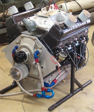
Because the Enderle fuel pump for the injectors is mounted facing forward on the front of the marine timing cover, it required a special drive fixture to be located on the front of the camshaft and camshaft sprocket. This involved more fabrication and ended up being a two piece affair which allows a hex drive to connect the camshaft to the pump. The original tach drive location on the marine cover not only provides a location for bolting up the Enderle fuel pump directly in front of the camshaft, the marine cover also permits the blower drive at the crankshaft to be placed closer to the engine which in turn further reduces any flex or deflection on the crankshaft snout caused by the blower belt.

The one component on this engine that remains relatively stock is the oil pump. The oil pump is a Dynagear P/N DM-42 which is a gerotor (gerorotor) style pump but utilizes a cast iron body instead of the aluminum body normally found on that same style of pump when offered by FoMoCo. The pump was simply disassembled, checked for any flaws and clearances checked, and reassembled with the only modification being the addition of a 0.150” shim on the bypass spring in order to boost the cold start oil pressure.
Engine break-in was performed on an engine dyno so the engine could be appropriately loaded but was done so before actually installing the 6-71 roots style blower on the engine. The break-in process was performed using standard carburetion rather than the blower setup; a Blue Thunder intake and a List #1850 600cfm Holley took care of this chore. After break-in, a single dyno pull was made with the carb in place which peaked 321 HP @ the 5750 rpm cut off point. Not too shabby for a 7½:1 compression ratio, being over cammed, and no carburetor or ignition timing adjustments.
The blower was then installed and subsequent dyno pulls were made. Due to ignition constraints, the engine was cutting out (ignition breaking up) after 5500 rpms but still managed to make 642 HP (6000rpm) and 644 lbs torque (4750rpm) before the ignition problems would ultimately terminate the dyno session. The ignition problems were eliminated when the engine was installed in the chassis by utilizing an MSD crank trigger ignition.

Although the engine is allowed to shift at 6500 rpms in the course of running it down the track, it has bumped the rpm limiter at 7800 rpms during the burnouts. Teardown of the bottom end to check bearings after a number of quarter mile passes still had everything looking fresh and new even with the given amount of alcohol that was making its way into the pan. So far, so good, and continues to make quarter mile passes with minimal problems.


Originally published in Y-Block Magazine, Issue #76, SEPT-OCT 2006
Addendum: As of this writing, the best et has been an 8.15 second pass at National Trails Dragway. There have been a multitude of low eight second passes at Texas Motorplex in Ennis but all these have been with the tires breaking loose at mid track and the car just coasting thru the traps. Even the addition of a wing did not help. Final conclusion is that the chassis is simply too stiff along with the wheel base being too short for this combination. T.E.