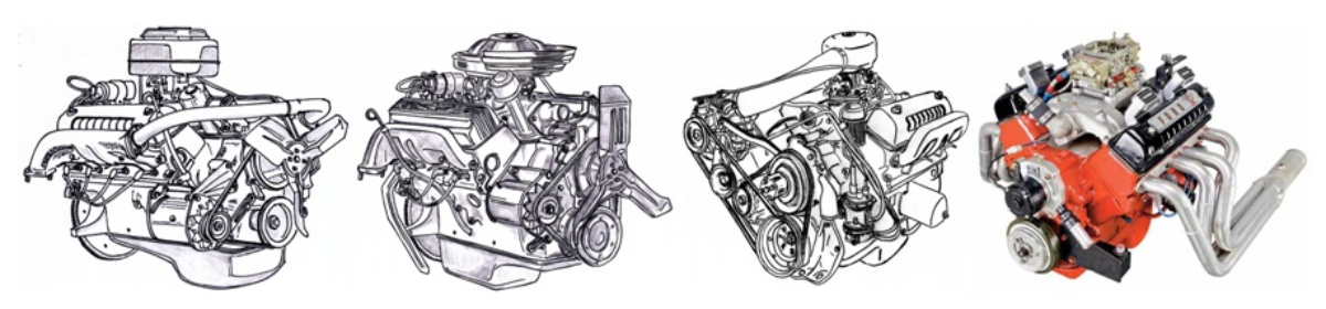
Rocker arm geometry is an area that’s very often overlooked when modifying an engine for increased power output and/or efficiency. Besides the obvious advantage of reducing valve stem and guide wear by minimizing the “scrubbing” action that can take place when the rocker arm geometry is optimized, the maximum or advertised lift at the valve for a given camshaft profile can also be obtained. The method in which the rocker arm geometry is altered will vary depending upon the valve train design. There are basically two rocker arm support designs where the rocker arms are either a ball (fulcrum) and stud arrangement or are shaft mounted. To adjust the rocker arm geometry on the ball and stud style, the length of the pushrod itself is altered in order to change the pivot point but when dealing with a shaft mounted rocker arm such as on our venerable Y-Block or an Fe Ford, then the height of the pedestal stand holding the rocker shaft must be altered.
In the case of the Y-Block, rocker arm geometry whether it’s good or bad, doesn’t change when the heads and/or deck is machined. The relationship of the rocker shaft to the valve stem tips remains the same and the pushrod length only needs changing when required by lieu of the lash adjuster being outside of its usable range. On an engine using the ball and stud arrangement for its rocker arms, any machining done to the head or deck surfaces can necessitate a change in pushrod length to maintain the existing rocker arm ratio.
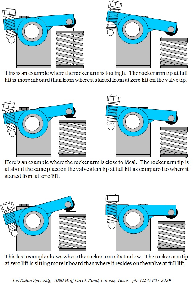
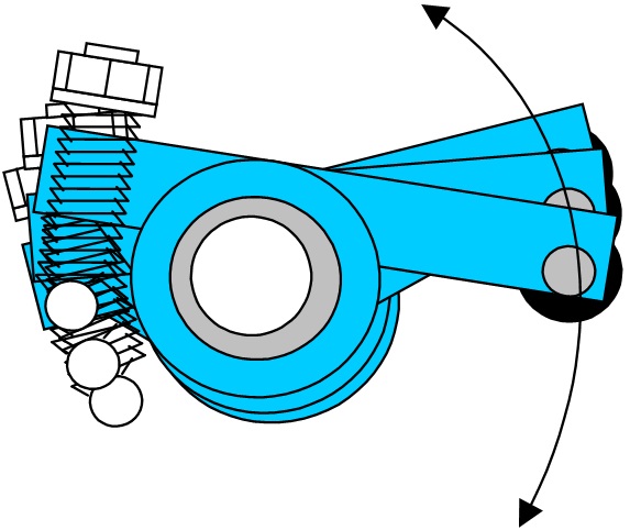 Rocker arm geometry is generally optimal when the travel or movement of the rocker arm tip on the valve stem is minimized. To understand how to achieve correct geometry, it must be understood that the rocker arm tip itself travels in an arc. At zero lift, the rocker arm tip is expected to be closer (or inboard) to the plane of the pivot point and as the valve starts moving down, the rocker arm tip starts moving outboard. If the geometry is close to ideal, then the rocker tip will be at its most outboard position at half or mid lift at which point the rocker tip starts moving inboard again as the valve reaches full lift. Simply put, ideal rocker arm geometry is achieved when the rocker tip is sitting on the valve stem tip at the same position at both zero lift and full lift. In a perfect world where the rocker shaft pedestal stand locating holes, the valve guide, and the rocker itself are all machined to exact specifications, the rocker tip is expected to be sitting slightly inboard of the valve stem center at both zero and full lift while the rocker tip will be sitting the same distance outboard of the center of the valve stem at exactly mid-lift. But because of variances in manufacture, getting the rocker arm to sit on the valve tip in the desired location while optimizing the rocker arm geometry doesn’t always happen. In these cases, lash caps may be utilized to increase the area on the tip of the valve stem in which to increase the working area but in other cases it may require another style of rocker arm of the same ratio. Depending upon the scenario, compromises may be made in which optimum geometry is not achieved in order to allow the rocker tip to be sufficiently located on the valve stem tip.
Now that it’s clear that the rocker tip must be sitting on the valve tip at the same location at both zero lift and full lift, then it’s easy to assume that the rocker arms pivot point most be raised or lowered if the rocker arm tip contacts the valve stem too far inboard or outboard at zero lift in relation to where the tip resides at full lift. In the case of the Y-Block with its shaft mounted rockers, this involves altering the height of the pedestal stands so that the rocker shaft can be moved in the appropriate direction. If the rocker arm tips are sitting too far inboard or closer to the shaft versus where the tip sits at full lift, then the pedestal stands need to be longer or sitting taller. Conversely, if the rocker arm tips are sitting too far outboard as compared to where they reside at full lift, then the pedestal stands need to be shortened. In extreme cases, altering the height of the shafts can require an appropriate change in pushrod lengths to insure adjustability at the rocker arm for valve lash adjustment.
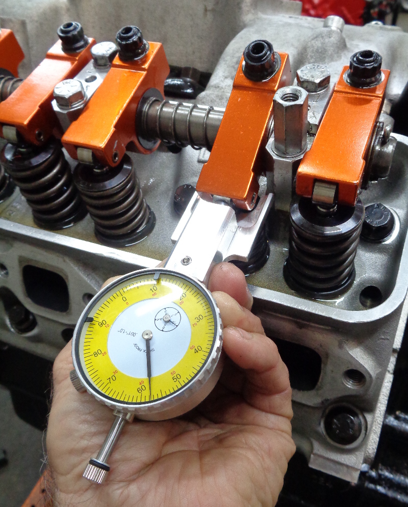
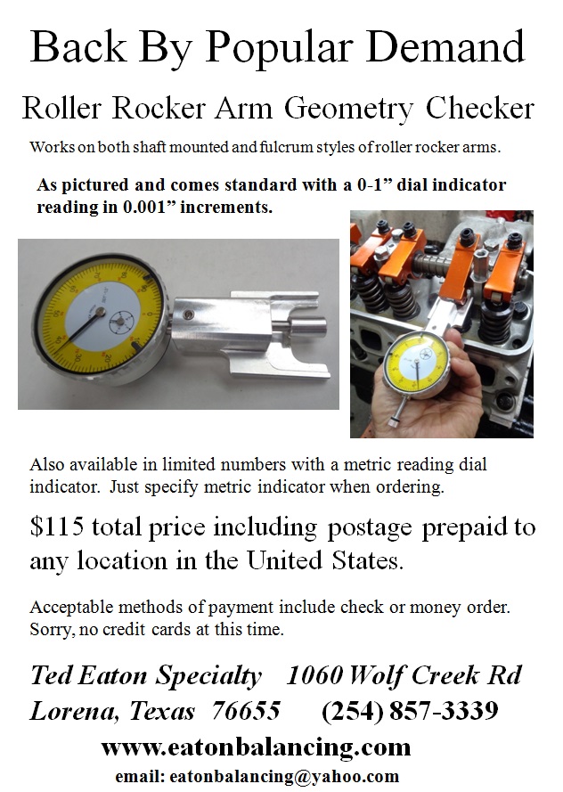
There are several different methods in which to measure rocker arm geometry. Without any measuring tools available, a visual observation of the rocker arm movement while the valve is going through its range of motion can prove quite adequate. Using a dye or magic marker on the valve stem tips to indicate the path or length of travel on those tips while varying the height of the rocker shaft can also indicate better or worse rocker arm geometry. Measuring the actual valve lift can also be performed as maximum valve lift occurs at “perfect” geometry and if the rocker is above or below this ideal point, then the valve lift starts decreasing logarithmically by the amount that the geometry is incorrect. There are tools available to facilitate measuring rocker arm geometry and one of these is a dial indicator on a fixture that actually measures the relationship of the rocker tip and with the edge of the valve stem at both zero and full lift. Regardless of the method used, the end result remains the same where the contact point of the rocker tip with the valve stem at both zero lift and full lift are being made the same.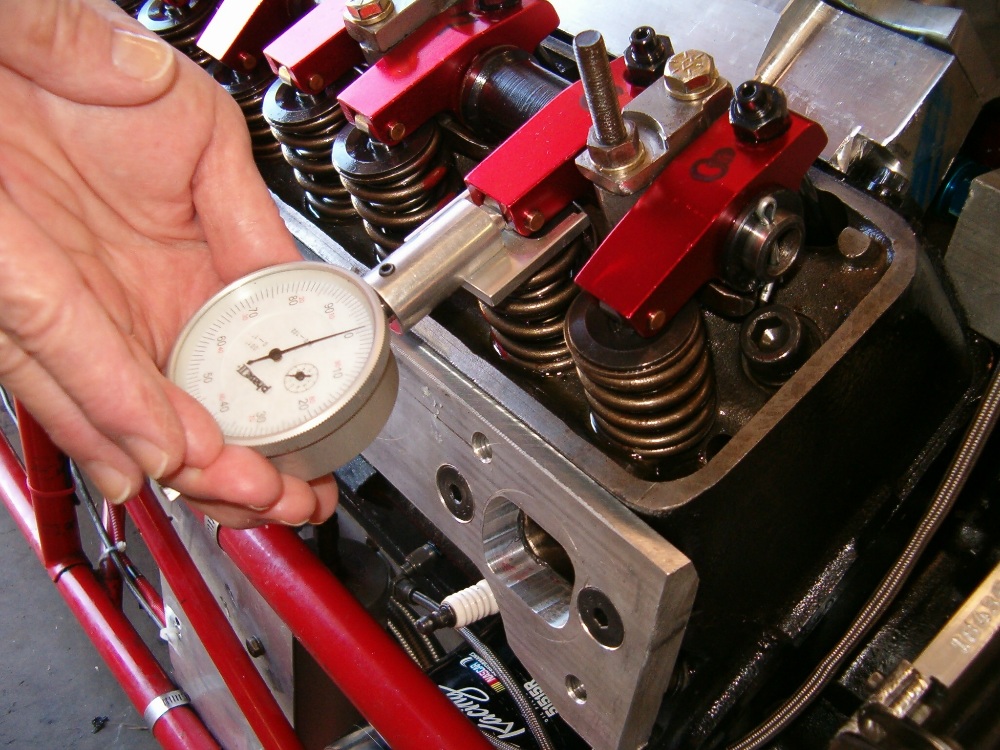
As delivered from Ford, the rocker geometry on the Y engine is reasonably close with the stock lift camshafts. As the stock camshafts are replaced with those with increased lift, then it becomes necessary to machine the rocker shaft pedestal bases so that the shaft itself sits lower to re-achieve a more ideal rocker arm geometry. Because of the variability in the various rockers from the different manufacturers, it would be difficult to have a set amount that would need to be removed from the stands for a given amount of lift. Even using aftermarket or replacement valves with different than stock valve stem lengths will dictate checking the rocker arm geometry and correcting as deemed necessary. Due to all the variables involved, it would be prudent to at least check the rocker arm geometry on an engine as it’s being assembled especially when new valves, rocker arms, and possibly rocker shaft assemblies are being replaced.. T.E
Click for larger image
Originally published in Y-Block Magazine, Sep-Oct 2005, Issue #70.
2022 May 19 Addendum: The rocker arm geometry checker pictured above is currently available. Here’s the link giving the details on how to order.
1Z-Rocker-Arm-Geometry-Checker.jpg (632×889) (eatonbalancing.com)